
Dust cleaning device

A technology for cleaning devices and dust, applied in cleaning methods and utensils, cleaning methods using gas flow, removing smoke and dust, etc., can solve the problems of high labor intensity of workers, harmful employees' health, and increased labor costs, and achieve a simple positioning process. Fast, low labor input cost, and low labor intensity for workers

Active Publication Date: 2021-12-03
BOZHON PRECISION IND TECH CO LTD
View PDF5 Cites 1 Cited by
  • Summary
  • Abstract
  • Description
  • Claims
  • Application Information

AI Technical Summary

Problems solved by technology

[0002] During the production and processing of parts, due to the large amount of floating dust in the production workshop or processing environment or after the parts have been placed for a long time, more dust will be deposited on the surface of the parts Dust, especially for those shell parts with larger external areas, before these parts are processed or assembled in the next step, the dust on the surface of these parts needs to be removed to ensure the quality and surface finish of the product; but in the prior art In the process of cleaning the dust on the surface of parts, manual wiping is usually used, but due to the continuous improvement of production capacity, manual wiping can no longer meet the needs of mass production, and manual wiping has greatly increased labor costs. increase, the labor intensity of the workers is high, and the willingness to work is low; some use brushes to brush off the dust on the parts or use a blower to blow off the dust to achieve the purpose of dust removal on the surface of the parts, but this is easy to cause the dust to diffuse on the surface of the parts. In the air, the air is polluted, the air quality is reduced, and it is harmful to the health of employees. Moreover, the cleaning power of these dust removal methods is poor, which may easily lead to incomplete dust removal. Moreover, the dust removal efficiency of this method is relatively low, and it is difficult to adapt to batches. streamlined production; therefore, those skilled in the art urgently need to solve the problems existing in the prior art

Method used


Image

  • Dust cleaning device
  • Dust cleaning device
  • Dust cleaning device

Examples


Embodiment Construction

[0036] The present invention will be further described below in conjunction with the accompanying drawings and specific embodiments, so that those skilled in the art can better understand the present invention and implement it, but the examples given are not intended to limit the present invention.

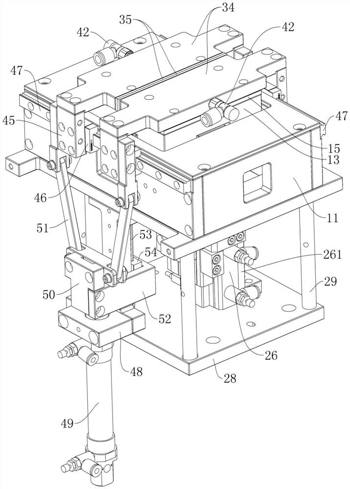
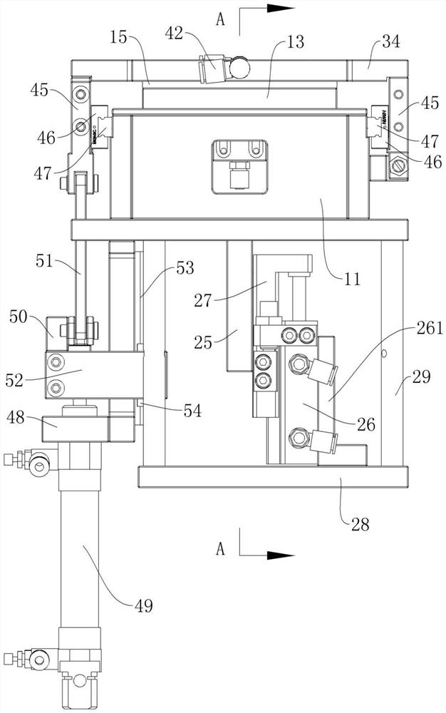
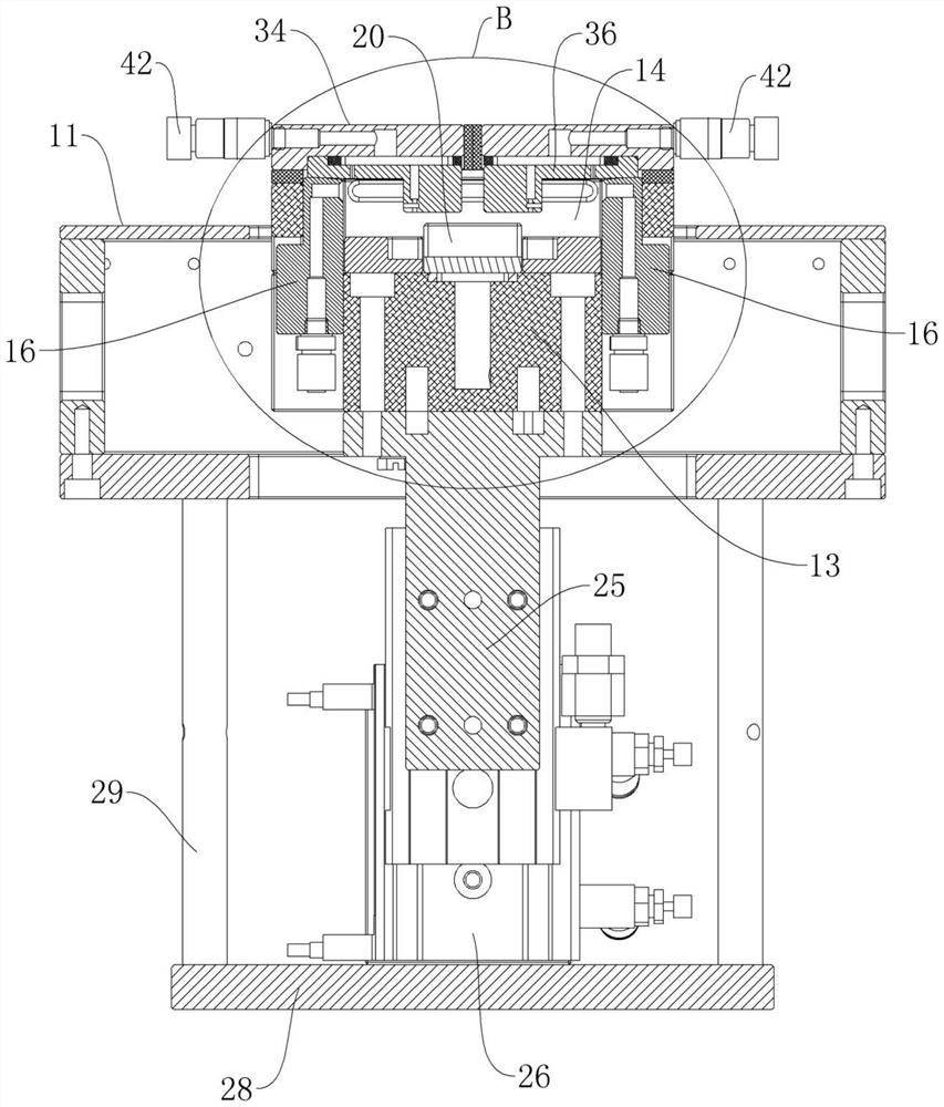
[0037] refer to Figure 1-Figure 16 Shown, an embodiment of a kind of dust cleaning device of the present invention;

[0038] refer to Figure 1-Figure 4 As shown, a dust cleaning device includes: a cleaning platform 13, the cleaning platform 13 is installed on the main housing 11, and the cleaning platform 13 is provided with a cleaning tank 14 for holding workpieces. The cleaning tank 14 is provided with a negative pressure dust suction assembly for discharging the dust inside;

[0039]Sealing cover plate, the sealing cover plate is movably connected on the main housing 11, the positive pressure dust removal assembly for cleaning the dust on the surface of the workpiece is arr...


PUM


Abstract

The invention discloses a dust cleaning device which comprises a cleaning platform deck and a sealing cover plate. The cleaning platform deck is installed on a main shell, a cleaning groove used for containing workpieces is formed in the cleaning platform deck, and a negative pressure dust suction assembly used for discharging dust in the cleaning groove is arranged in the cleaning groove. The sealing cover plate is movably connected to the main shell, a positive pressure dust removal assembly used for cleaning dust on the surfaces of the workpieces is arranged on the sealing cover plate, a driving mechanism for driving the sealing cover plate to move is further connected to the sealing cover plate, and the workpieces to be subjected to dust removal are placed in the cleaning groove. A driving mechanism drives the sealing cover plate to move so as to seal the cleaning groove, dust on the surfaces of the workpieces in the cleaning groove is removed through the positive pressure dust removal assembly, and the negative pressure dust suction assembly discharges dust removed from the workpieces out of the cleaning groove. The workpieces to be cleaned are placed in the closed cleaning groove for positive pressure dust removal, the cleaning effect is good, dust pollution is avoided, and meanwhile the dust cleaning device is suitable for assembly line automatic production.

Description

technical field [0001] The invention relates to the technical field of cleaning equipment, in particular to a dust cleaning device. Background technique [0002] During the production and processing of parts, due to the large amount of floating dust in the production workshop or processing environment or after the parts have been stored for a long time, more dust will be deposited on the surface of the parts, especially for those shell parts with large external areas. Before the parts are processed or assembled in the next step, the dust on the surface of these parts needs to be removed to ensure the quality and surface finish of the product; but in the prior art, in the process of cleaning the dust on the surface of the parts, usually using The way of manual wiping, but due to the continuous improvement of production capacity, the method of manual wiping can no longer meet the needs of mass production, and the way of manual wiping greatly increases the labor cost, the labor...

Claims


Application Information

Patent Timeline
Patent Type & Authority Applications(China)
IPC IPC(8): B08B5/02B08B13/00B08B15/04
CPCB08B5/02B08B13/00B08B15/04
Inventor 王莽
Owner BOZHON PRECISION IND TECH CO LTD
Learn More