A punching device suitable for pump body

A punching and pump body technology, used in drilling/drilling equipment, metal processing equipment, boring/drilling, etc., can solve the problem that the distance between the threaded drill and the pump body cannot be flexibly adjusted, and the maximum adjustment height of the set components cannot be changed. , maintenance and cleaning process are cumbersome and other problems, to achieve the effect of easy maintenance and cleaning, avoid sudden drop, and expand the use function

Active Publication Date: 2022-08-02
江苏鑫沪莱泵业有限公司
View PDF0 Cites 0 Cited by
  • Summary
  • Abstract
  • Description
  • Claims
  • Application Information

AI Technical Summary

Problems solved by technology

[0004] The purpose of the present invention is to provide a kind of punching equipment suitable for the pump body of the water pump, to solve the punching equipment on the market proposed in the above background technology, most of them cannot flexibly adjust the distance between the threaded drill bit and the pump body, and the punching processing accuracy Insufficient, the pump body is easily damaged, the maximum adjustment height of the set assembly on the punching assembly cannot be changed, and installation and adjustment cannot be performed according to the model size of the pump body, it is inconvenient to install and disassemble, the maintenance and cleaning process is cumbersome, and local shaking and The problem of deviation

Method used


Image

  • A punching device suitable for pump body
  • A punching device suitable for pump body
  • A punching device suitable for pump body

Examples


Embodiment 1

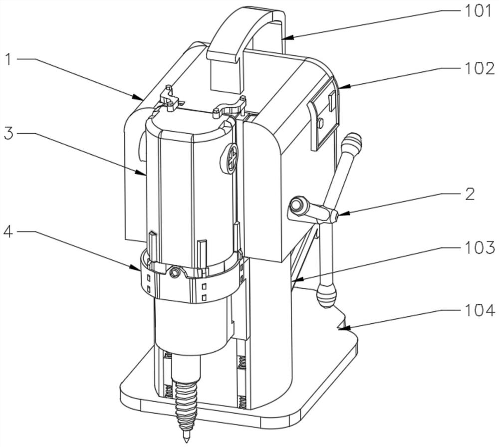
[0030] Example 1: see Figure 1-11 , the present invention provides a technical solution for punching equipment suitable for the pump body: including a punching assembly 1, one side of the punching assembly 1 is installed with a shaft 2 for rotating and adjusting the vertical height of the drilling machine 3, the punching A drilling machine 3 for providing drilling power is installed in the middle of one end of the assembly 1, one side of the drilling machine 3 and one end of the punching assembly 1 is provided with a set assembly 4 for installing the drilling machine 3, the shaft 2 One side is connected with a linkage assembly 10 for rotating linkage.

[0031] like Figure 10-11 As shown, the shaft 2 includes a screw head 21 threadedly connected to it, one side of the punching assembly 1 is provided with a rod hole 1002 corresponding to the shaft 2, and three sets of hinges are arranged around the outer surface of the shaft 2 in an equilateral triangle shape. 22. One end of...

Embodiment 2

[0033] Example 2: as Figure 1-11 As shown, it includes a punching assembly 1, one side of the punching assembly 1 is installed with a shaft 2 for rotating and adjusting the vertical height of the drilling machine 3, and one end of the punching assembly 1 is installed in the middle position for providing drilling power. The drilling machine 3 is provided with a sleeve assembly 4 for installing the drilling machine 3 on one side of the drilling machine 3 and at one end of the punching assembly 1 , and a linkage assembly 10 for rotational linkage is connected to one side of the shaft 2 .

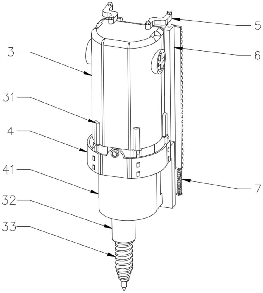
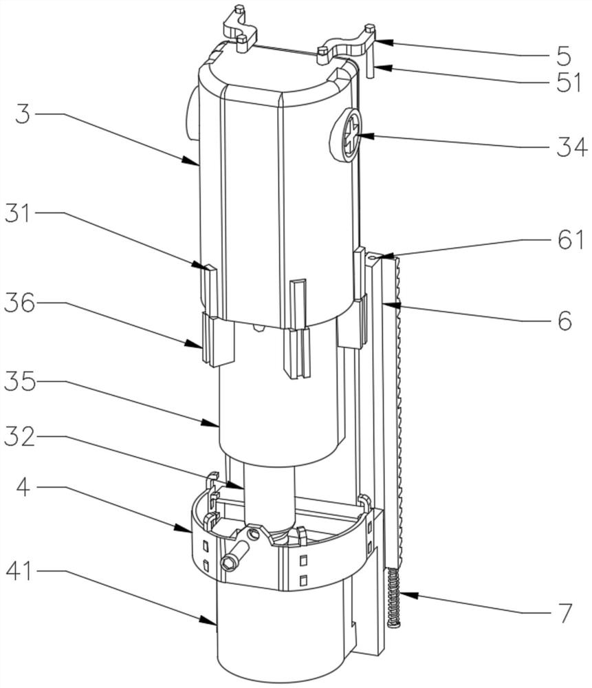
[0034] like Figure 2-5 As shown, the sleeve assembly 4 includes an inner cavity cylinder 41 for docking the sleeve power regulator 35, wherein the power regulator 35 is used to adjust the output power of the drilling machine 3, and a convex wall is fixed in the middle of one end of the inner cavity cylinder 41 42, its surface is provided with bolt holes, one end of the convex wall 42 and the...

Embodiment 3

[0037] Example 3: as Figure 1-11 As shown, it includes a punching assembly 1, one side of the punching assembly 1 is installed with a shaft 2 for rotating and adjusting the vertical height of the drilling machine 3, and one end of the punching assembly 1 is installed in the middle position for providing drilling power. The drilling machine 3 is provided with a sleeve assembly 4 for installing the drilling machine 3 on one side of the drilling machine 3 and at one end of the punching assembly 1 , and a linkage assembly 10 for rotational linkage is connected to one side of the shaft 2 .

[0038] like Figure 1-9 As shown, the inner side of the T-shaped groove 105 is installed with a first pressure block 8 for supporting and buffering, the lower end of the first pressure block 8 is connected with three sets of elastic rod assemblies 1 81 on both sides, and the lower end of the first pressure block 8 passes through the elastic rod. The component one 81 is provided with a second ...


PUM


Abstract

The invention discloses a punching device suitable for a water pump pump body, which relates to the technical field of water pump pump body processing. Rod, a drilling machine for providing drilling power is installed in the middle of one end of the punching assembly; the punching equipment can be adjusted at will to change the distance between the threaded drill and the pump body, and always maintain the sleeve assembly and the punching assembly. The dynamic balance relationship between the threaded bits can avoid the sudden drop of the threaded drill bit, ensure the processing precision of the punching equipment, prevent the threaded drill bit from hitting the pump body, and effectively change the maximum adjustment height of the set assembly on the punching assembly. Installation and adjustment, easy installation and disassembly, easy maintenance and cleaning, strong integrity, not easy to shake and deviation, guaranteed punching quality of the pump body, can automatically adjust the rotational speed of the threaded drill bit, and realize the punching process of the pump body of different thicknesses .

Description

technical field [0001] The invention relates to the technical field of water pump body processing, in particular to a punching device suitable for a water pump body. Background technique [0002] With the development of high and new technology, the application fields of punching machines are more and more extensive, from the initial defense field and aerospace field to machinery, medical and other fields; according to the shape of the processed materials, punching machines are divided into flat punching machines Hole punching machine, round tube punching machine, square tube punching machine and U-shaped steel punching machine, etc. According to the needs of different industries, different parts and their thicknesses, a variety of lightweight, professional, bill and factory are designed. Type of punching machine, in order to adapt to the trend of the times and meet the needs of the market, the punching machine is developing in the direction of beauty and efficiency; the punc...

Claims


Application Information

Patent Timeline
Patent Type & Authority Patents(China)
IPC IPC(8): B23B45/00B23B41/00
CPCB23B45/003B23B45/008B23B41/00
Inventor 仇亚新
Owner 江苏鑫沪莱泵业有限公司
Why Eureka
Try Eureka