
Fixing device for projectile product cabin section welding

A technology of fixing device and rocket chamber, applied in auxiliary devices, welding equipment, auxiliary welding equipment, etc., can solve the problems of poor operation comfort, difficult to control the lifting speed, and the height of the operation position is not adjustable, so as to improve the comfort and reduce the The effect of labor intensity

Pending Publication Date: 2021-12-03
西安现代控制技术研究所
View PDF0 Cites 0 Cited by
  • Summary
  • Abstract
  • Description
  • Claims
  • Application Information

AI Technical Summary

Problems solved by technology

At present, in the trial production stage of the product, the production of the cable network in the upper compartment of the bomb is done after the installation of the components in the cabin is completed, the loose wire ends of the electrical connectors of each component are led out, and manual welding is carried out at the hatch. Due to the welding workload Generally, it takes 1-2 days. There are two methods currently used: one is to place the cabin section on the operating table for welding, but it is necessary to find and modify the corresponding foam and other cushioning materials to place and protect the cabin section. , the height of the operating position cannot be adjusted, and the circumferential rotation can only be achieved by moving the product. This method generally requires the operator to stand up and work, which is poor in operating comfort, and it is easy to cause fatigue and lead to hidden dangers in product quality.
The second is to weld it on the existing hydraulic lifting round chair. Although the height and circumferential rotation can be adjusted, the lifting speed is difficult to control, and there are no protective measures in the circumferential direction, which is easy to cause sliding or dumping, and there are safety and quality risks.

Method used


Image

  • Fixing device for projectile product cabin section welding
  • Fixing device for projectile product cabin section welding
  • Fixing device for projectile product cabin section welding

Examples


Embodiment 1

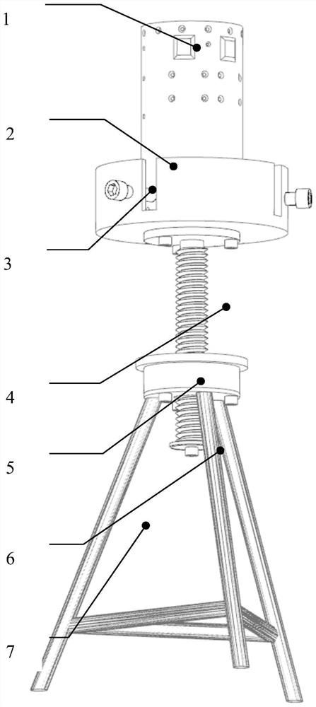
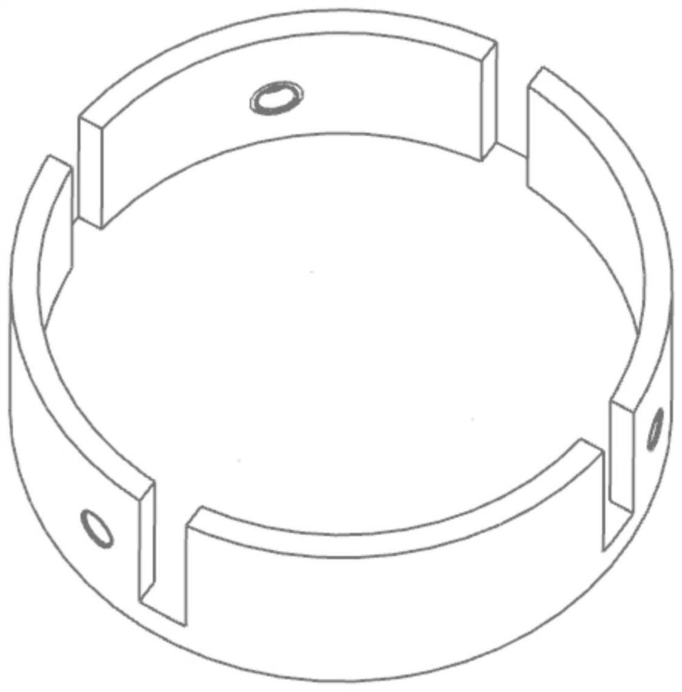
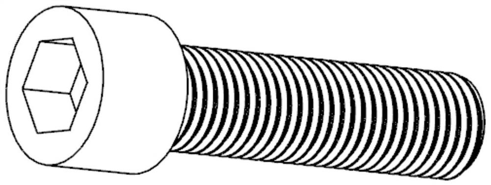
[0049] In this example, if Figure 1-Figure 7As shown, when a certain type of anti-aircraft missile instrument cabin 1 needs to be butt welded, the instrument cabin 1 is first placed on the tray 2, and the three fastening screws 3 are adjusted according to the outer diameter of the cabin to lock the cabin to prevent slipping. The rubber pad at the end of the fixing screw 3 can compress the cabin body without scratching the outer surface of the cabin body, which is simple, reliable and easy to operate. Then, according to their own conditions, the operator rotates the tray 2 clockwise or counterclockwise, and uses the threaded connection between the screw rod 4 and the base 5 to adjust and lock the height of the tray 2 to meet his own comfort requirements. Compared with the lifting method, the cost is low, reliable, and the lifting and locking operations are convenient. When the highest height is reached, the function of the baffle 6 is used to prevent the screw 4 from the base ...


PUM

PropertyMeasurementUnit
Heightaaaaaaaaaa

Abstract

The invention belongs to the technical field of electric assembly of projectile products, and particularly relates to a fixing device for projectile product cabin section welding. The fixing device comprises a bottom frame, a base, a screw rod, baffle, a trays and fastening screws. Compared with the prior art, the fixing device for projectile product cabin section welding is suitable for fixing cabin section in the missile cabin section butt welding and wiring and binding technological process, and is mainly used for improving the operation comfort of personnel in the missile cabin section welding process, reducing the labor intensity and guaranteeing the product quality and the process safety at the same time. The fixing device is reliable in lifting and locking, simple and convenient to operate and wide in popularization and application space. The fixing device has the advantages that (1), the trays and the fastening screws are combined to realize placement and locking of cabins with different outer diameters; and (2), the screw rod, the base and the baffle plate are adopted to form a lifting mechanism of the device, so that the heights of the trays can be freely adjusted and locked within a certain range, the comfort degree in the operation process is improved, and the labor intensity is reduced.

Description

technical field [0001] The invention belongs to the technical field of electrical assembly of ammunition and arrow products, and in particular relates to a fixing device for welding and assembling cabin sections of ammunition and arrow products. Background technique [0002] The cable network system on the missile is the "nerve and blood vessel" of the missile, which ensures the transmission of electrical energy and electrical signals on the missile, and plays a very important role in the realization of the entire missile function. The welding of the missile product compartment mainly refers to the operation process such as wire welding, wiring and related electrical assembly of the internal electrical components of the instrument cabin and control cabin. At present, in the trial production stage of the product, the production of the cable network in the upper compartment of the bomb is done after the installation of the components in the cabin is completed, the loose wire e...

Claims


Application Information

Patent Timeline
IPC IPC(8): B23K37/047
CPCB23K37/047
Inventor 李文昊祁小斌郑向阳刘辉杨倩王治平席晓文杨毅石金珂蒲瑶李倩王宝亮郑媛张挺柳林梁家驹应嘉奇刘殷杰徐潇杰王万礼姬云鹏
Owner 西安现代控制技术研究所
Learn More