Mechanical fixed-distance separation device
A separation device and fixed-distance technology, applied in metal processing and other directions, can solve problems affecting product quality, ear strap length deviation, non-compliance with product standards, etc.
- Summary
- Abstract
- Description
- Claims
- Application Information
AI Technical Summary
Problems solved by technology
Method used
Image
Examples
Embodiment 1
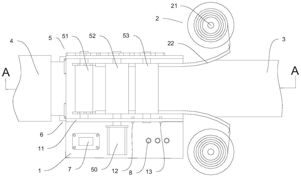
[0029] In this example, if figure 1 As shown, the present invention is used for welding and fixed-distance separation of the ear straps of the strap-type mask. Specifically, the present invention is installed between the feed line 3 and the discharge line 4, and the feed line 3 is used to provide The mask sheet body of the earband, the mask sheet body is covered with upper earbands on both sides in the feeding mechanism 2, and the welding is completed in the traction mechanism 5, and then the fixed distance separation of the earbands is realized by the separation mechanism 6, and the separated belts The mouth mask sheet body that ear band is arranged enters next process by discharge line 4.
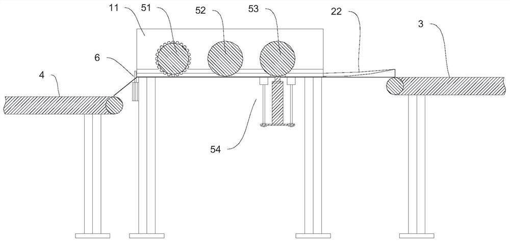
[0030] In this example, if Figure 1~3 As shown, a mechanical fixed-distance separation device includes a mounting base 1, a feeding mechanism 2, a traction mechanism 5, a separation mechanism 6 and a controller 7. Two vertical plates 11 are arranged on the mounting base 1, and the tract...
Embodiment 2
[0042] This embodiment provides an optional solution for the specific structure of the separation mechanism 6 on the basis of the first embodiment.
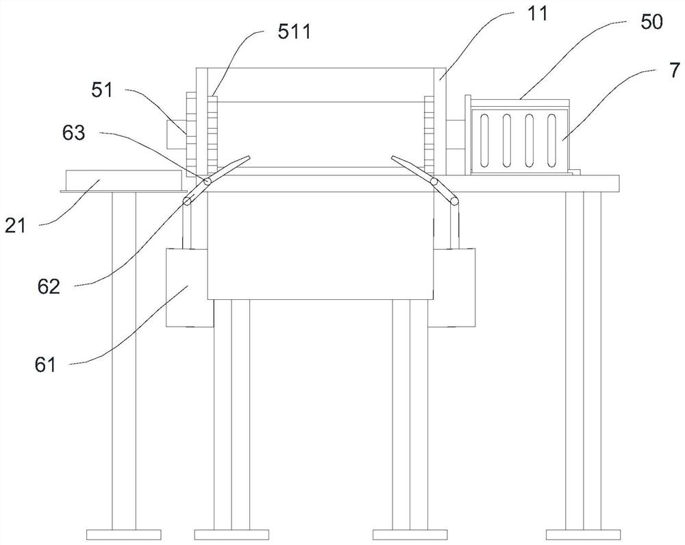
[0043] In this example, if image 3 As shown, both sides of the outlet end of the traction mechanism 5 are equipped with a separation mechanism 6. The separation mechanism 6 includes a cutting drive mechanism 61 and a cutter 62. The middle part of the cutter 62 is rotatably mounted on the mounting seat 1 through a connecting piece 63. One end of the cutter 62 It is connected with the cutting drive mechanism 61 , the other end of the cutter 62 is the cutting end, and the connecting piece 63 is located at both ends of the discharge port of the traction mechanism 5 .
[0044] In this embodiment, specifically, the cutting driving mechanism 61 is an air cylinder, and several support frames are arranged at the bottom of the installation base 1 , the air cylinder is installed on the support frames, and the movable shaft of the air cylin...
Embodiment 3
[0048] This embodiment provides an optional solution for the specific structure of the feeding mechanism 2 on the basis of any of the above embodiments.
[0049] In this example, if figure 1 As shown, the feeding mechanism 2 includes a feeding tray 21 and a material guide rail 22. The center of the feeding tray 21 is provided with a rotating shaft, and the material is sleeved on the rotating shaft. Turn and rotate the discharging, and the guide rail 22 is used to guide the material.
[0050] In this embodiment, specifically, the material guide rail 22 gradually narrows from one end of the tray 21 to one end of the third traction roller 53, and the material is an ear belt, and the ear belt enters the material guide rail 22 before the ear belt It is a wide single-layer ear strap. As the material guide rail 22 gradually narrows, the ear strap that enters the traction mechanism 5 is folded into a double-layer ear strap, and the mask sheet enters the double-layer ear strap from th...
PUM
 Abstract
Description
Claims
Application Information
 - R&D
- Intellectual Property
- Life Sciences
- Materials
- Tech Scout
- Unparalleled Data Quality
- Higher Quality Content
- 60% Fewer Hallucinations
Browse by: Latest US Patents, China's latest patents, Technical Efficacy Thesaurus, Application Domain, Technology Topic, Popular Technical Reports.
© 2025 PatSnap. All rights reserved.Legal|Privacy policy|Modern Slavery Act Transparency Statement|Sitemap|About US| Contact US: help@patsnap.com


