Forward and reverse switching device and forward and reverse switching method thereof

A forward-reverse and forward-rotating technology, applied in transmission, gear transmission, transmission control, etc., can solve the problems of reducing forward-reverse switching efficiency, narrow torque variation range, small rotational speed variation range, etc. The effect of reverse switching efficiency, less number of gear meshes, and simple system structure

Pending Publication Date: 2021-12-03
BEIJING INSTITUTE OF TECHNOLOGYGY
View PDF2 Cites 0 Cited by
  • Summary
  • Abstract
  • Description
  • Claims
  • Application Information

AI Technical Summary

Problems solved by technology

[0007] 1) The speed variation range is small;
[0008] 2) The range of torque variation is narrow;
[0009] 3) The engine cannot be reversed;
[0010] 4) It cannot output power at low speed, that is, it cannot start with load
[0012] The above contradictions require that the engine performance be modified or adjusted in the process of transmission system design to meet the driving needs of the vehicle. The vehicle needs to frequently switch the power direction during work, while the ordinary reversing mechanism uses a pair of gear pairs or a The planetary row achieves reversing, and the reversing method is simple in structure, which cannot well meet the high-speed reversing driving requirements of the vehicle.
[0013] The application number is "201320070066.9", and the utility model patent titled "a forward and reverse switching gearbox" discloses a forward and reverse mechanism, including a box body, which is equipped with an input shaft and an output shaft, and also includes a switching unit , the switching unit includes a sliding part, two output switching mechanisms and an adjusting mechanism respectively fixed on the sliding part, the sliding part is slidably installed in the box, and the adjusting mechanism controls and connects the sliding part; Mechanism and reverse output mechanism, the forward output mechanism and reverse output mechanism are respectively set at positions that match the input shaft and output shaft, and the forward output mechanism or reverse output mechanism and the input shaft are selected by controlling the movement of the sliding parts. Linkage to achieve the purpose of switching forward and reverse rotation, but in the switching process, it is necessary to control the gear on the input shaft to stop rotating to complete the switching, otherwise, when switching, the gear with certain motion on the input shaft and the output without motion The gears on the mechanism will have a speed difference, and then the teeth will be hit when meshing, which will greatly reduce the service life of the gears, and the time required for the gears to stop-switch-start again is longer, which reduces the forward and reverse switching s efficiency
[0014] The application number is "201811445846.0", and the invention patent titled "a double internal meshing forward and backward mechanism" discloses a forward and backward mechanism, including: an input shaft, an output shaft, and a housing composed of a left housing and a right housing , the double internal meshing planetary row, clutch and brake installed in the housing; the double internal meshing planetary row includes: planet carrier, ring gear, connecting piece, planetary gear with internal and external teeth and sun gear; clutch includes: disc spring, left end of clutch Friction plate, middle friction plate of clutch, friction plate at right end of clutch and outer hub of clutch; brake includes: wave spring, friction plate at left end of brake, middle friction plate of brake, friction plate at right end of brake and piston, through linkage between brake and clutch, control planetary gear The forward or reverse output of the planetary gear, but because the moment between the ring gear, the planetary gear and the sun gear in the planetary gear is relatively short, the internal force between each gear is relatively large during transmission, which reduces the life of the gear. It is not applicable in the scene of forward and backward switching

Method used


Image

  • Forward and reverse switching device and forward and reverse switching method thereof
  • Forward and reverse switching device and forward and reverse switching method thereof
  • Forward and reverse switching device and forward and reverse switching method thereof

Examples


Embodiment Construction

[0038] The following will clearly and completely describe the technical solutions in the embodiments of the present invention with reference to the accompanying drawings in the embodiments of the present invention. Obviously, the described embodiments are only some, not all, embodiments of the present invention. Based on the embodiments of the present invention, all other embodiments obtained by persons of ordinary skill in the art without making creative efforts belong to the protection scope of the present invention.

[0039] The purpose of the present invention is to provide a forward-reversing device and its forward-reversing switching method to solve the problems existing in the prior art, which can perform forward-reversing switching without stopping the machine, improve the reversing efficiency, and have a long service life.

[0040] In order to make the above objects, features and advantages of the present invention more comprehensible, the present invention will be fur...


PUM


Abstract

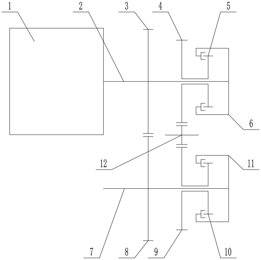
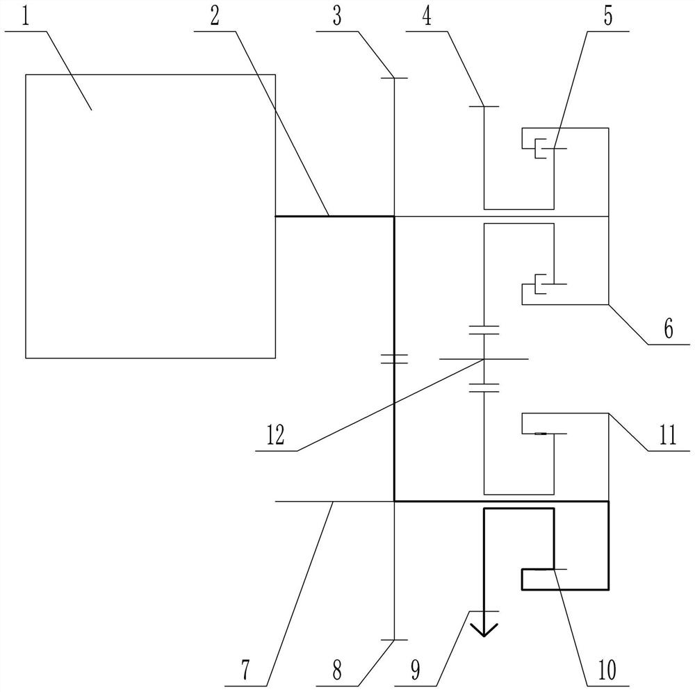
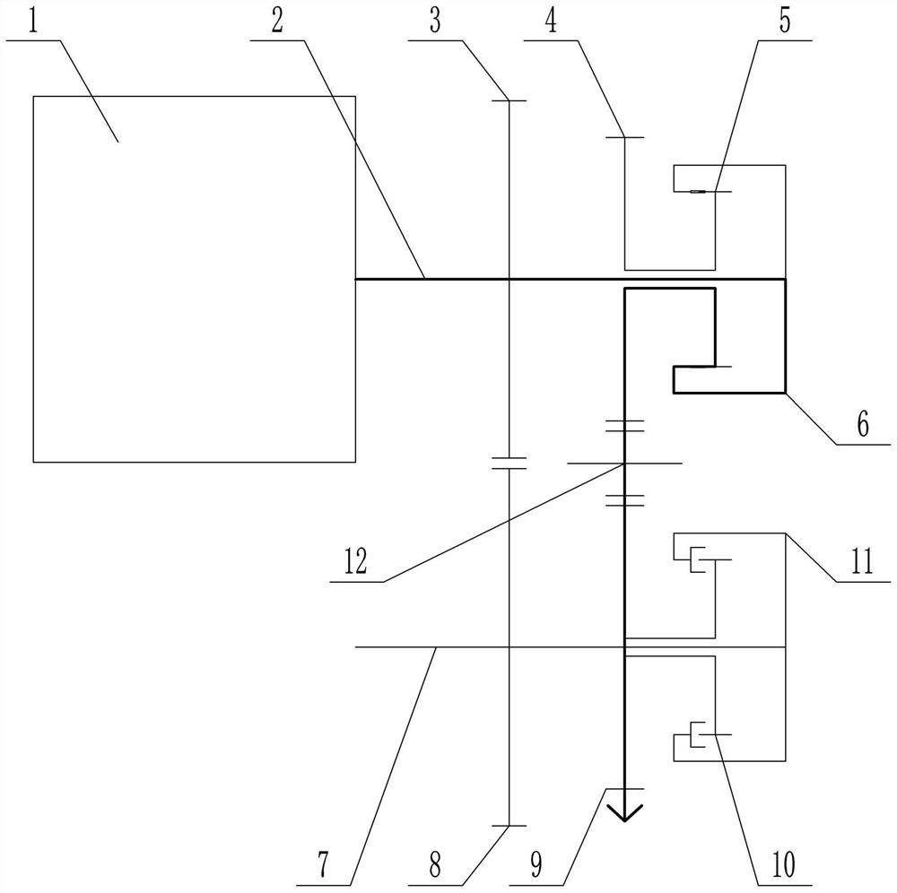
The invention discloses a forward and reverse switching device and a forward and reverse switching method thereof, and relates to the field of vehicle transmission equipment. The forward and reverse switching device comprises a first transmission mechanism and a second transmission mechanism; the first transmission mechanism comprises a first rotating shaft, a first gear, a second gear, a third gear and a first friction driver; the third gear is connected to the first rotating shaft through the first friction driver; the second transmission mechanism comprises a second rotating shaft, a fourth gear, a fifth gear, a sixth gear and a second friction driver; the sixth gear is connected to the second rotating shaft through the second friction driver; the first gear is externally meshed with the fourth gear; and the second gear is externally meshed with the fifth gear through an idle gear. According to the forward and reverse switching device and the forward and reverse switching method thereof, the first transmission mechanism or the second transmission mechanism is selected to carry out rotary transmission through switching between the combined state and the separated state of two clutches, transmission gears are in an engaged state in the whole switching process, forward and reverse switching can be carried out in a non-stop state, and the forward and reverse switching efficiency is improved.

Description

technical field [0001] The invention relates to the field of vehicle transmission equipment, in particular to a forward and reverse device and a forward and reverse switching method thereof. Background technique [0002] The forward and reverse mechanism is generally located behind the engine and before the gearbox. A reasonable transmission ratio distribution can be achieved through a reasonable design of the forward and reverse mechanism. The basic requirements for the transmission system are: [0003] 1) It can drive backwards, and some vehicles require high-speed reverse driving; [0004] 2) It can cut off the power to start the engine or brake the vehicle; [0005] 3) It can quickly consume the kinetic energy of the vehicle to perform deceleration and parking brake. [0006] However, the insufficient performance of the power plant is mainly reflected in the following points: [0007] 1) The speed variation range is small; [0008] 2) The range of torque variation is...

Claims


Application Information

Patent Timeline
Patent Type & Authority Applications(China)
IPC IPC(8): F16H3/40F16H61/04
CPCF16H3/40F16H61/04F16H2003/0818F16H2003/0811
Inventor 韩立金刘辉许日明李智鹏徐丽丽
Owner BEIJING INSTITUTE OF TECHNOLOGYGY
Why Eureka
Try Eureka