
Actuating piece and reversing valve

A technology for actuating parts and reversing valves, which is applied to engine components, multi-port valves, valve devices, etc., can solve the problems of poor control and driving effects, inability to adjust the valve flow area, and complex structure of the driving parts, and achieve a simple structure. Effect

Active Publication Date: 2021-12-03
BYD CO LTD
View PDF8 Cites 2 Cited by
  • Summary
  • Abstract
  • Description
  • Claims
  • Application Information

AI Technical Summary

Problems solved by technology

However, the current electronic water valve has a very complicated structure for controlling the driving parts of the valve, and it is impossible to adjust the flow area of ​​the valve, the control and driving effect is poor, and the complexity of the system is high.

Method used


Image

  • Actuating piece and reversing valve
  • Actuating piece and reversing valve
  • Actuating piece and reversing valve

Examples


Embodiment Construction

[0032] Specific embodiments of the present disclosure will be described in detail below in conjunction with the accompanying drawings. It should be understood that the specific embodiments described here are only used to illustrate and explain the present disclosure, and are not intended to limit the present disclosure.

[0033] In this disclosure, in the absence of a contrary statement, the used orientation words such as "up and down" can refer to Figure 4 Orientation shown on the drawing. "Top" corresponds to Figure 4 The directions shown "top", "bottom" and "bottom" correspond to Figure 4 The direction shown is "down". "Inside and outside" refer to the inside and outside of the outline of the relevant parts. In addition, the terms "first", "second" and the like used in the embodiments of the present disclosure are used to distinguish one element from another element, and do not have sequence or importance.

[0034] In order to distribute the flow of the liquid flowi...


PUM


Abstract

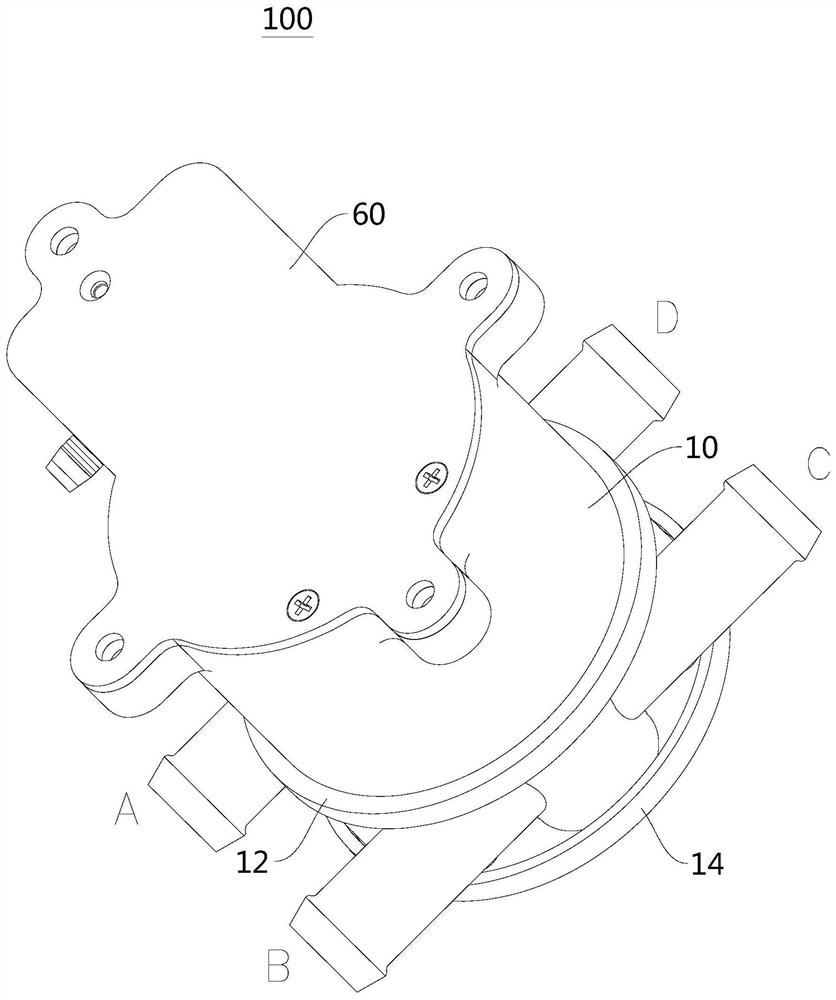
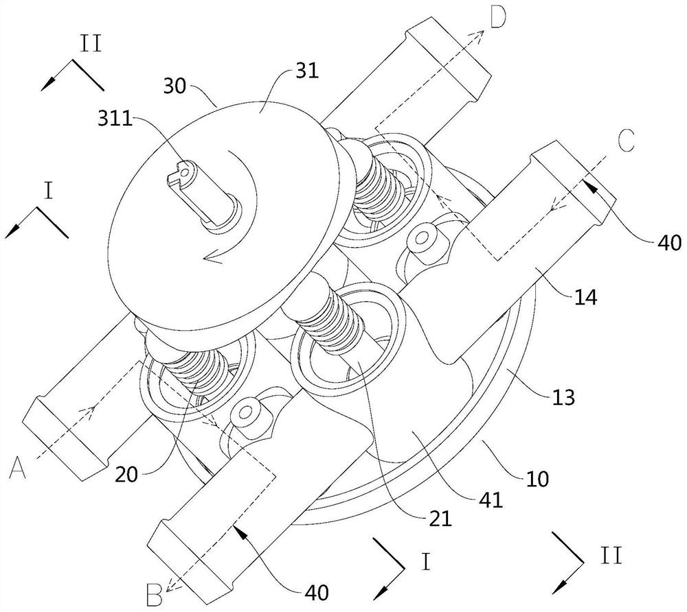
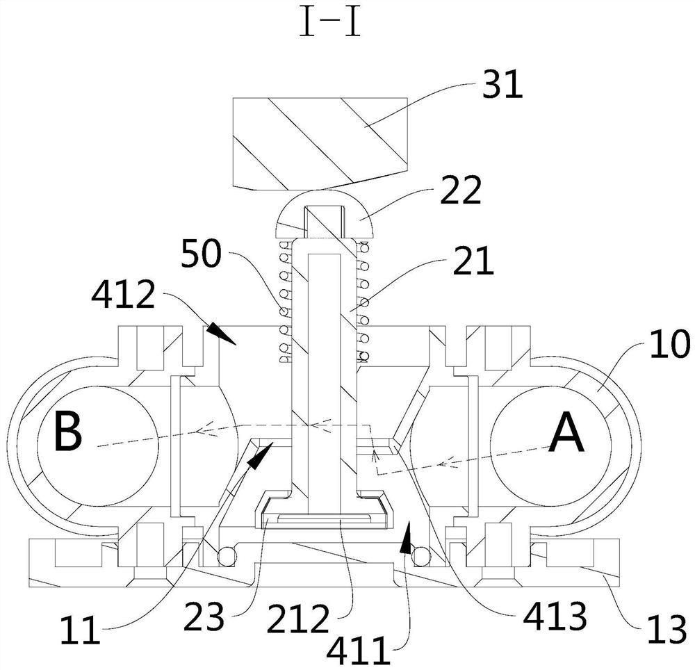
The discloses relates to an actuating piece and a reversing valve. The actuating piece acts on a valve element rod of the reversing valve; the actuating piece is provided with a guide surface; a guide path is formed on the guide surface; the guide surface is used for being pressed against the top end of the valve element rod in a sliding manner, so that the top end of the valve element rod can be selectively pressed against the positions at different heights on the guide path to adjust the position of the valve element rod in a valve port of the reversing valve, thereby changing the flow area at the valve port. According to the technical scheme, the actuating piece can adjust the flow area of the valve port of the reversing valve, so that the flow direction of liquid in the reversing valve can be switched or the flow of the liquid flowing through the reversing valve can be distributed.

Description

technical field [0001] The present disclosure relates to the field of electric vehicle thermal management systems, in particular, to an actuator and a reversing valve. Background technique [0002] The electric vehicle thermal management system includes a coolant circulation system. Some vehicles only have one PTC heater. When the ambient temperature is low, the PTC heater needs to provide heated coolant for the heater core and power battery pack at the same time. , At this time, it is necessary to properly distribute the coolant output by the PTC heater. However, the current electronic water valve has a very complicated structure for controlling the driving part of the valve, and cannot adjust the flow area of ​​the valve, the control and driving effect is poor, and the complexity of the system is high. Contents of the invention [0003] The purpose of the present disclosure is to provide an actuator and a reversing valve, the actuating member can adjust the flow area at...

Claims


Application Information

Patent Timeline
Patent Type & Authority Applications(China)
IPC IPC(8): F16K11/16F16K27/02F16K31/60B60H1/00B60L58/24B60K11/02B60K1/00
CPCF16K11/165F16K27/0263F16K31/60B60H1/00485B60L58/24B60K11/02B60K1/00B60K2001/006B60K2001/005Y02T10/70Y02T10/12
Inventor 刘文策
Owner BYD CO LTD
Learn More