Air energy water heating device with water purification function

A technology of hot water device and air energy heat pump, which is applied to the feeding/discharging device of settling tank, fluid heater, lighting and heating equipment, etc. Dry burning and other problems to achieve the effect of increasing the speed

Active Publication Date: 2021-12-03
恒海环保科技(贵州)有限公司
View PDF5 Cites 1 Cited by
  • Summary
  • Abstract
  • Description
  • Claims
  • Application Information

AI Technical Summary

Problems solved by technology

[0005] Aiming at the deficiencies of the prior art, the present invention provides an air-energy water heating device with water purification function, which can continuously and rapidly heat the water body, so that the air-energy water heater can continuously produce hot water, and the pressure of the external water source is relatively high. When it is low, it can cut off the hot water and place it for dry burning. It solves the problem that it takes a certain amount of time for the heat released by the condenser to exchange heat with the water in the water tank. When the pressure is low, the water in the water tank is easy to empty, which leads to the problem of dry burning of the air energy hot water device

Method used


Image

  • Air energy water heating device with water purification function
  • Air energy water heating device with water purification function
  • Air energy water heating device with water purification function

Examples


Embodiment 1

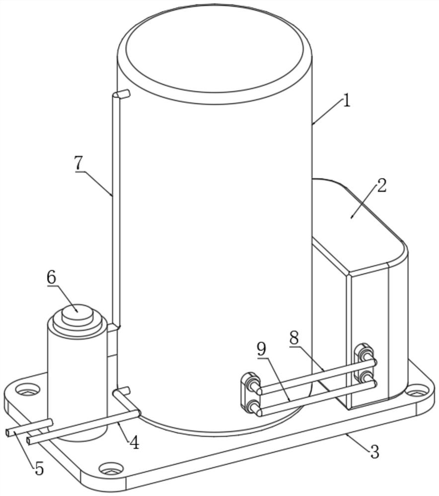
[0029] Refer to attached Figure 1-8, an air energy hot water device with water purification function, comprising a bottom plate 3, an air energy heat pump unit 2, a water purifier 6 and an insulated water tank 1, and the air energy heat pump unit 2, the water purifier 6 and the insulated water tank 1 are all fixedly connected Above the bottom plate 3, the upper left end of the thermal insulation water tank 1 is fixedly connected to the drainpipe 7, and one end of the drainpipe 7 is fixedly connected to a standpipe 10, and one end of the drainpipe 7 is fixedly connected to the water inlet end of the water purifier 6, and the water is purified. The drain end of the device 6 is fixedly connected with a hot water pipe 5, and the lower left end of the thermal insulation water tank 1 is fixedly connected with a water inlet pipe 4 through a round hole, and the thermal insulation water tank 1 is fixedly connected with a housing 13, and the upper end of the housing 13 is fixed through ...

Embodiment 2

[0031] Embodiment 2: the difference based on Embodiment 1 is;

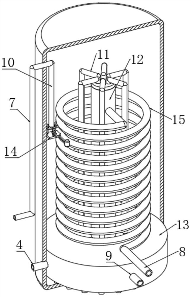
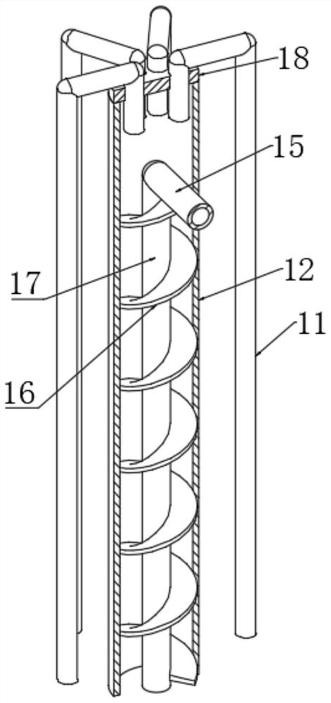
[0032] Refer to attached Figure 2-7 , the heat exchange mechanism includes a vortex plate 21, the upper and lower ends of the vortex plate 21 are respectively fixedly connected with the inner walls of the upper and lower ends of the housing 13, and a heat exchange channel 19 is formed between the vortex plate 21 and the inner wall of the housing 13, and A vortex tube 20 is arranged in the hot channel 19, and one end of the vortex tube 20 is fixedly connected with a conduit 17, and the upper end of the conduit 17 extends into the casing 12, and one end of the heat exchange coil 15 passes through the wall of the casing 12 and It is fixedly connected with the upper end of the conduit 17, the pipe wall of the conduit 17 is fixedly connected with a spiral copper sheet 16, the spiral copper sheet 16 is socketed with the inner wall of the casing 12, and the spiral copper sheet 16 and the inner wall of the casing 12 toge...

Embodiment 3

[0034] Embodiment 3: the difference based on embodiment 1 is;

[0035] Refer to attached Figure 8 , the protective mechanism includes a top plate 25, the upper end of the top plate 25 is fixedly connected with a rubber sheet 31, the side wall of the top plate 25 is fixedly connected with two sliding sleeves 24 through through holes, and the positioning shafts 32 are sleeved in the two sliding sleeves 24, and The shaft wall of the positioning shaft 32 is fixedly connected with the positioning ring 30, the lower end of the positioning shaft 32 is fixedly connected with the upper end of the support plate 14, and the upper end of the support plate 14 is fixedly connected with two support blocks 29, and the opposite side of the two support blocks 29 Rotately be connected with transmission rod 27 by rotating shaft, one end of transmission rod 27 is fixedly connected with float 28, and the other end of transmission rod 27 is connected with pull rod 26 by pin rotation, and the upper ...


PUM


Abstract

The invention relates to the technical field of water heaters, and discloses an air energy water heating device with a water purification function, which comprises a bottom plate, an air energy heat pump unit, a water purifier and a heat preservation water tank; the air energy heat pump unit, the water purifier and the heat preservation water tank are fixedly connected above the bottom plate; the upper side of the left end of the heat preservation water tank is fixedly connected with a drainage pipe; one end of the drainage pipe is fixedly connected with a vertical pipe; one end of the drainage pipe is fixedly connected with the water inlet end of the water purifier; the drainage end of the water purifier is fixedly connected with a hot water pipe; the lower side of the left end of the heat preservation water tank is fixedly connected with a water inlet pipe through a round hole; a shell is fixedly connected into the heat preservation water tank; the upper end of the shell is fixedly connected with a sleeve through the round hole; and the side wall of the sleeve is sleeved with a heat exchange coil pipe. According to the air energy water heating device with the water purification function provided by the invention, water can be continuously and rapidly heated, so that an air energy water heater can continuously produce hot water, and hot water supply can be stopped when the pressure of an external water source is low so as to prevent dry burning.

Description

technical field [0001] The invention relates to the technical field of water heaters, in particular to an air-energy water heating device with water purification function. Background technique [0002] Air energy water heater, also known as air source heat pump water heater, its working principle is very similar to that of air conditioner. It uses a small amount of electric energy to drive the compressor to run. The gaseous working medium is compressed by the compressor into a high-temperature, high-pressure liquid, then enters the condenser and exchanges heat with the water stored in the water tank, and then heats the water for daily use, and is compatible with solar water heaters In comparison, air-energy water heaters are very convenient. They can be used whether they are installed indoors or outdoors, and regardless of cloudy or sunny days, and the temperature is above zero degrees Celsius. In addition, after a tank of water is used up, the air-energy water heater only n...

Claims


Application Information

Patent Timeline
Patent Type & Authority Applications(China)
IPC IPC(8): F24H4/04F24H9/16F24H9/18F24H9/20B01D21/02B01D21/24
CPCF24H4/04F24H9/16F24H9/1809F24H9/2007B01D21/02B01D21/245
Inventor 苏波
Owner 恒海环保科技(贵州)有限公司
Why Eureka
Try Eureka