Compact transformer

A transformer, a compact technology, applied in the field of transformers, can solve the problems of affecting the use effect, increasing the labor intensity of the staff, damage to the internal components of the transformer, etc., to achieve the effect of improving the heat dissipation effect, reducing the shaking phenomenon, and improving the protection performance.

Pending Publication Date: 2021-12-03
JIANGXI MINGZHENG SUSTION EQUIP
View PDF0 Cites 0 Cited by
  • Summary
  • Abstract
  • Description
  • Claims
  • Application Information

AI Technical Summary

Problems solved by technology

[0003] Existing high-frequency transformers are usually packaged individually after production, and then transported. However, the existing outer packaging of transformers only has simple protection and aesthetic functions. The internal components of the transformer are damaged and the pins are bent, which affects the use effect. At the same time, during the installation process of the existing transformer, the pins are usually inserted into the circuit board, and then the transformer is manually supported, and then the connection between the pins and the circuit board is checked one by one. Welding requires staff to support the transformer for a long time during the whole process, which increases the labor intensity of the staff and is not easy to use. At the same time, the existing transformer usually does not have the active heat dissipation function during the use process, and the internal temperature of the transformer is too high to easily damage its internal components. , affect the service life, so we introduced a compact transformer to solve the above problems

Method used


Image

  • Compact transformer
  • Compact transformer
  • Compact transformer

Examples


Embodiment Construction

[0035] The following will clearly and completely describe the technical solutions in the embodiments of the present invention in conjunction with the accompanying drawings in the embodiments of the present invention;

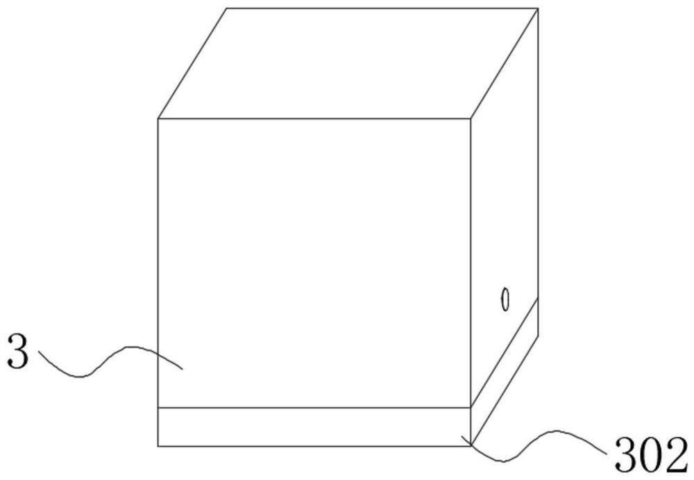
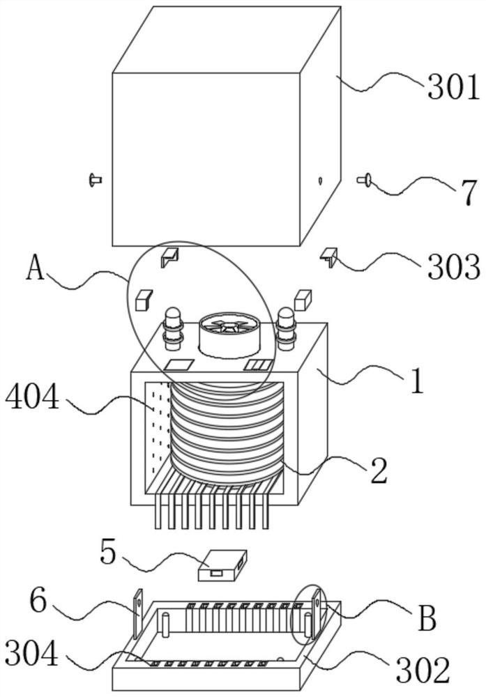
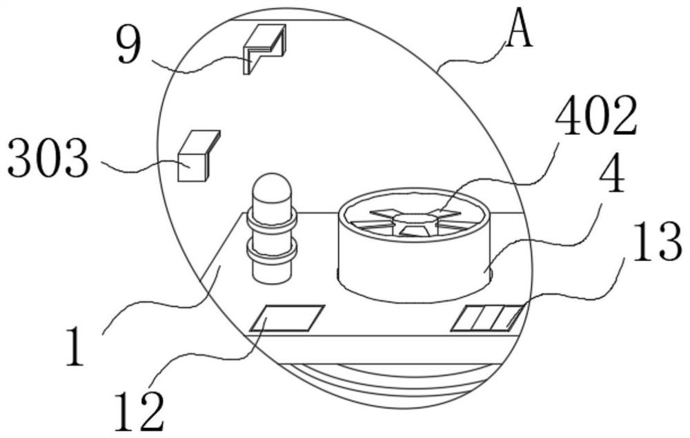
[0036] see Figure 1-8 , in the present invention, a compact transformer includes a housing 1, a transformer body 2 is installed inside and outside the housing 1, a protective assembly 3 is provided on the outside of the housing 1, a heat dissipation assembly 4 is provided inside and outside the housing 1, and the housing 1 is provided with a positioning component 5 at the bottom.

[0037] In the present invention, according to the case 1 and the transformer body 2 being a high-frequency transformer body, the setting of the protective component 3 facilitates the protection of the transformer body 2 during transportation, and reduces the occurrence of internal component damage and pin bending. Using the setting of the positioning component 5, it is convenient to...


PUM


Abstract

The invention discloses a compact transformer, and belongs to the field of transformers, the compact transformer comprises a shell, transformer main bodies are mounted in and on the outer side of the shell, a protection assembly is arranged on the outer side of the shell, heat dissipation assemblies are arranged in and on the outer side of the shell, and a positioning assembly is arranged at the bottom of the shell. According to the transformer, the transformer can be well protected, the phenomena that elements in the transformer are damaged and pins are bent in the transfer process are reduced, meanwhile, a positioning function is achieved when the transformer is installed, workers do not need to support the transformer for a long time, the labor intensity of the workers is reduced, and the installation efficiency is conveniently improved; in the using process, heat dissipation can be actively conducted, the phenomenon that the temperature in the transformer is too high is reduced, and the service life of the transformer is prolonged.

Description

technical field [0001] The invention relates to the field of transformers, in particular to a compact transformer. Background technique [0002] High-frequency transformer is a power transformer whose working frequency exceeds intermediate frequency (10kHz). It is mainly used as high-frequency switching power transformer in high-frequency switching power supply, and also used as high-frequency inverter in high-frequency inverter power supply and high-frequency inverter welding machine. power transformer. [0003] Existing high-frequency transformers are usually packaged individually after production, and then transported. However, the existing outer packaging of transformers only has simple protection and aesthetic functions. The internal components of the transformer are damaged and the pins are bent, which affects the use effect. At the same time, during the installation process of the existing transformer, the pins are usually inserted into the circuit board, and then th...

Claims


Application Information

Patent Timeline
Patent Type & Authority Applications(China)
IPC IPC(8): H01F19/04H01F27/02H01F27/06H01F27/08H01F27/29
CPCH01F27/02H01F27/022H01F27/025H01F27/06H01F27/292H01F27/085H01F19/04H01F2027/065H01F2027/297
Inventor 孙建辉李红梅陈维新孙涛林森
Owner JIANGXI MINGZHENG SUSTION EQUIP
Why Eureka
Try Eureka