Supercharge Your Innovation With Domain-Expert AI Agents!

an rc oscillating circuit

A technology of oscillating circuit and delay circuit, applied in the field of electronics, can solve the problems of increasing design difficulty, increasing circuit area and power consumption cost, etc.

Active Publication Date: 2022-02-11
LANSUS TECH INC
View PDF0 Cites 0 Cited by
  • Summary
  • Abstract
  • Description
  • Claims
  • Application Information

AI Technical Summary

Problems solved by technology

Increase circuit area and power consumption cost, and increase design difficulty

Method used


Image

  • an rc oscillating circuit
  • an rc oscillating circuit
  • an rc oscillating circuit

Examples


Embodiment 1

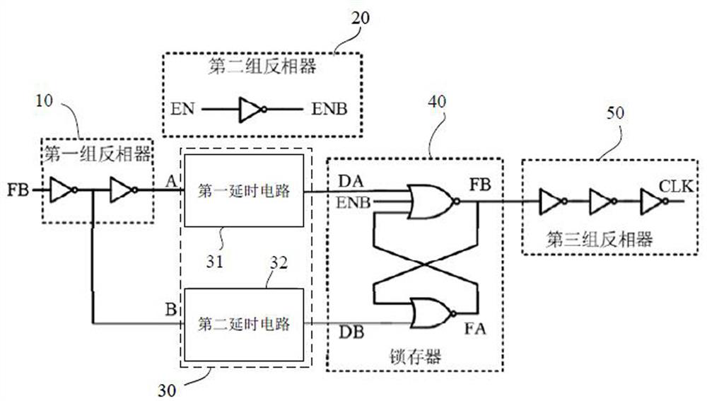
[0033] see figure 1 As shown, the embodiment of the present invention provides an RC oscillator circuit, including: a first set of inverters 10, a second set of inverters 20, a latch 40, a delay circuit 30, and a third set of inverters 50 .

[0034] Wherein, the first group of inverters 10 is connected to the delay circuit 30, which is used to generate two first signal A and second signal B with opposite potentials, and input to the delay circuit 30; The input terminal of the second group of inverters 20 is connected to the enable signal EN, and its output terminal is connected to the latch 40 for generating an inversion signal ENB opposite to the enable signal EN and inputting it to the Latch 40, the control circuit is enabled, and this enable is active at high level; the output end of the delay circuit 30 is connected to the latch 40, and is used for the first signal A and the second The second signal B is delayed, and the first delayed signal DA and the second delayed sig...

Embodiment 2

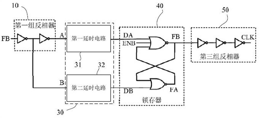
[0047] Such as image 3 Shown is an RC oscillator circuit provided by this embodiment. The difference from Embodiment 1 is that in this embodiment, the enable signal EN is active at low level. At this time, the enable signal is directly connected to the ENB of the latch. port, no need to set a second set of inverters.


PUM


Abstract

The present invention provides an RC oscillating circuit, comprising: a first group of inverters, a second group of inverters, a latch, a delay circuit, and a third group of inverters; the first group of inverters is connected to A delay circuit, which is used to generate two first signals A and a second signal B with opposite potentials; the input terminal of the second group of inverters is connected to the enable signal EN, and the output terminal thereof is connected to the latch; the delay circuit The output end of the latch is connected to the latch for delaying the first signal A and the second signal B; the latch is connected to a third group of inverters, which includes a first output end and a second output end, It receives the first delay signal DA and the second delay signal DB, and receives the first clock signal FB and the second clock signal FA generated by itself; after the first clock signal FB is driven by the third group of inverters The output signal CLK is output from its output terminal. The invention can avoid the unrecoverable situation after the circuit enters the dead state, and the circuit cost is low.

Description

technical field [0001] The invention relates to the field of electronic technology, in particular to an RC oscillator circuit. Background technique [0002] At present, the basic principle of the RC oscillator is to periodically charge and discharge the capacitor through the resistance. When the voltage on the capacitor reaches a certain level, the charging switch is controlled to be turned off through feedback, and the discharging switch is turned on. If only one capacitor is charged and discharged, it is generally controlled by a hysteresis comparator. If two sets of capacitors are charged and discharged, two comparators are used for feedback control. However, a comparator is basically required to judge the level and control the charging and discharging switch. [0003] Moreover, this way of using the comparator to judge the level must have the problem of output dead state. For example, the output node of the comparator reaches the middle level due to external force, an...

Claims


Application Information

Patent Timeline
Patent Type & Authority Patents(China)
IPC IPC(8): H03B5/06H03B5/04H03B5/08
CPCH03B5/06H03B5/04H03B5/08H03B5/20H03K3/0375H03K5/1565H03K3/037H03K5/135H03K19/20
Inventor 任小娇郭嘉帅
Owner LANSUS TECH INC
Features
  • R&D
  • Intellectual Property
  • Life Sciences
  • Materials
  • Tech Scout
  • Unparalleled Data Quality
  • Higher Quality Content
  • 60% Fewer Hallucinations
Learn More