
Intelligent reflector communication beam selection method based on beam index map

A technology of beam indexing and reflecting surfaces, which is applied in space transmit diversity, radio transmission systems, electrical components, etc., can solve the problems of reducing the communication rate, ignoring environmental factors, and many channel coefficients, so as to reduce overhead, strengthen flexibility, Wide range of effects

Active Publication Date: 2021-12-03
SOUTHEAST UNIV
View PDF5 Cites 2 Cited by
  • Summary
  • Abstract
  • Description
  • Claims
  • Application Information

AI Technical Summary

Problems solved by technology

However, since the smart reflector unit is passive and has no ability to send and receive pilot signals, and the smart reflector is composed of a large number of reflector units, there are many channel coefficients to be estimated, and channel estimation requires a large amount of pilot overhead, thus crowding out communication time, reducing the rate of communication
Some scholars have proposed to group smart reflector units for channel estimation, use different time scales to estimate the channels from the base station to the smart reflector and from the smart reflector to the user, and use the sparseness of the millimeter-wave channel to perform channel estimation with the help of compressed sensing. Estimation and other methods to reduce training overhead, but the number of pilots required by these methods increases with the number of antennas at the base station and the number of reflection units at the smart reflector
[0007] (3) The method based on the statistical model, which mainly models the channel based on the probability distribution of some channel parameters (channel gain, shadow fading, whether there is a line-of-sight link) or the information of the surrounding environment (building location and height). , but this method only uses the rough transceiver location information and signal propagation environment information, ignoring the environmental factors in the actual communication process, and there is a large deviation between the estimated channel and the actual channel

Method used


Image

  • Intelligent reflector communication beam selection method based on beam index map
  • Intelligent reflector communication beam selection method based on beam index map
  • Intelligent reflector communication beam selection method based on beam index map

Examples


Embodiment Construction

[0034] Reference will now be made in detail to the exemplary embodiments, examples of which are illustrated in the accompanying drawings.

[0035] Those skilled in the art can understand that, unless otherwise defined, all terms (including technical terms and scientific terms) used herein have the same meaning as commonly understood by those of ordinary skill in the art to which this invention belongs. It should also be understood that terms such as those defined in commonly used dictionaries should be understood to have a meaning consistent with the meaning in the context of the prior art, and will not be interpreted in an idealized or overly formal sense unless defined as herein Explanation.

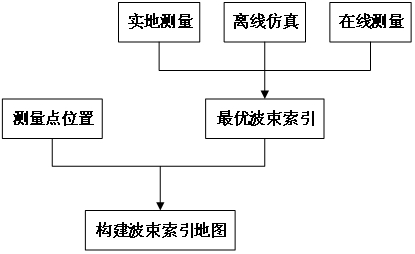
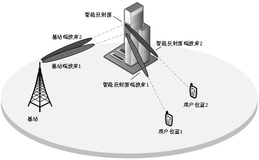
[0036]The present invention uses the beam index map to establish the mapping relationship between the user terminal position and the optimal beam pair at the base station end and the intelligent reflector end. For each user position in the service area, the beam index map can be based ...


PUM


Abstract

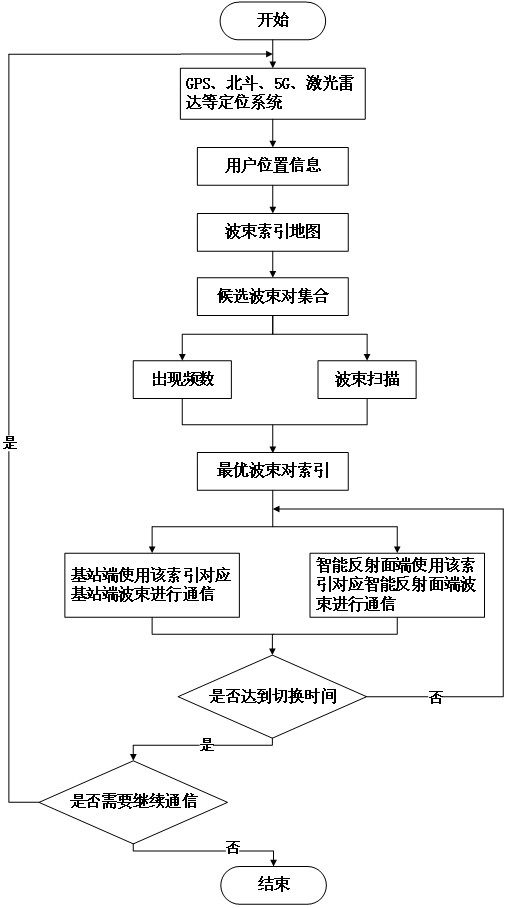
The invention discloses an intelligent reflector communication beam selection method based on a beam index map, which comprises the following steps: optimal beam pair information of a base station end and an intelligent reflector end corresponding to each user position are obtained, and an optimal beam index map is constructed and updated based on the user position in time; when the base station side communicates with a user through the intelligent reflecting surface, the user side acquires a real-time geographic position through multiple positioning modes, acquires a candidate beam pair set by means of the established beam index map, and directly performs beam selection or performs real-time beam scanning on the candidate beam pair set according to the occurrence frequency of different beam pairs; and therefore, intelligent reflector communication beam selection without channel training or lightweight channel training is realized. The method solves the problems that the intelligent reflector communication channel is high in estimation difficulty, a traditional beam scanning method is large in training overhead, and the training process is tedious, simplifies the real-time beam selection process, and greatly improves the effective communication rate.

Description

technical field [0001] The invention relates to the field of wireless communication standardization process, in particular to an intelligent reflection surface communication beam selection method based on a beam index map. Background technique [0002] The sixth generation (6G) mobile communication network facing 2030 needs to support ultra-high spectral efficiency and energy efficiency, ultra-wide wireless coverage and giant site connection, as well as ultra-high reliability and low-latency communication. Existing 5G technology is difficult to fully meet these requirements . Shortening the communication distance by adding more active nodes such as base stations, access points, and relays can improve network coverage and capacity, but it also leads to higher energy and hardware overhead, as well as more complex and severe problems. Interference issues; by using more antennas to obtain massive MIMO gain, the complexity of signal processing also increases; by using higher fre...

Claims


Application Information

Patent Timeline
Patent Type & Authority Applications(China)
IPC IPC(8): H04B7/06H04B7/08
CPCH04B7/0639H04B7/0695H04B7/088Y02D30/70
Inventor 曾勇丁丁杨吴迪金石张瑞
Owner SOUTHEAST UNIV
Learn More