Protective cover of monitoring equipment and protection method thereof

A technology of monitoring equipment and protective cover, applied in the field of monitoring equipment, can solve the problems of reducing heat dissipation efficiency, unstable center of gravity, inconvenient inspection and maintenance inside the protective shell, etc., to achieve the effect of improving cooling and preventing blockage

Pending Publication Date: 2021-12-03
王丽
View PDF2 Cites 0 Cited by
  • Summary
  • Abstract
  • Description
  • Claims
  • Application Information

AI Technical Summary

Problems solved by technology

[0004] The above existing technical solutions still have the following defects: the shock absorption effect is poor, it is not convenient to rotate it, the filter screen is easily blocked, which reduces the efficiency of heat dissipation, and it is not convenient to detect the inside of the protective shell maintenance, which reduces the usefulness of its use;
[0005] In addition, although spring buffer devices are added to some existing camera shields, the monitoring range needs to be dynamically adjusted, and the weight of the camera assembly is much larger than its external shield, so the camera will cause its center of gravity to be unstable during the pitch angle adjustment process. In addition, if the external light of the camera is too dark or too bright, it will cause its shooting quality, and the adjustment of the ambient light is also required. The adjustment of the existing ambient light needs to change the orientation of the entire camera, but the orientation change will affect its shooting range

Method used


Image

  • Protective cover of monitoring equipment and protection method thereof
  • Protective cover of monitoring equipment and protection method thereof
  • Protective cover of monitoring equipment and protection method thereof

Examples


Embodiment

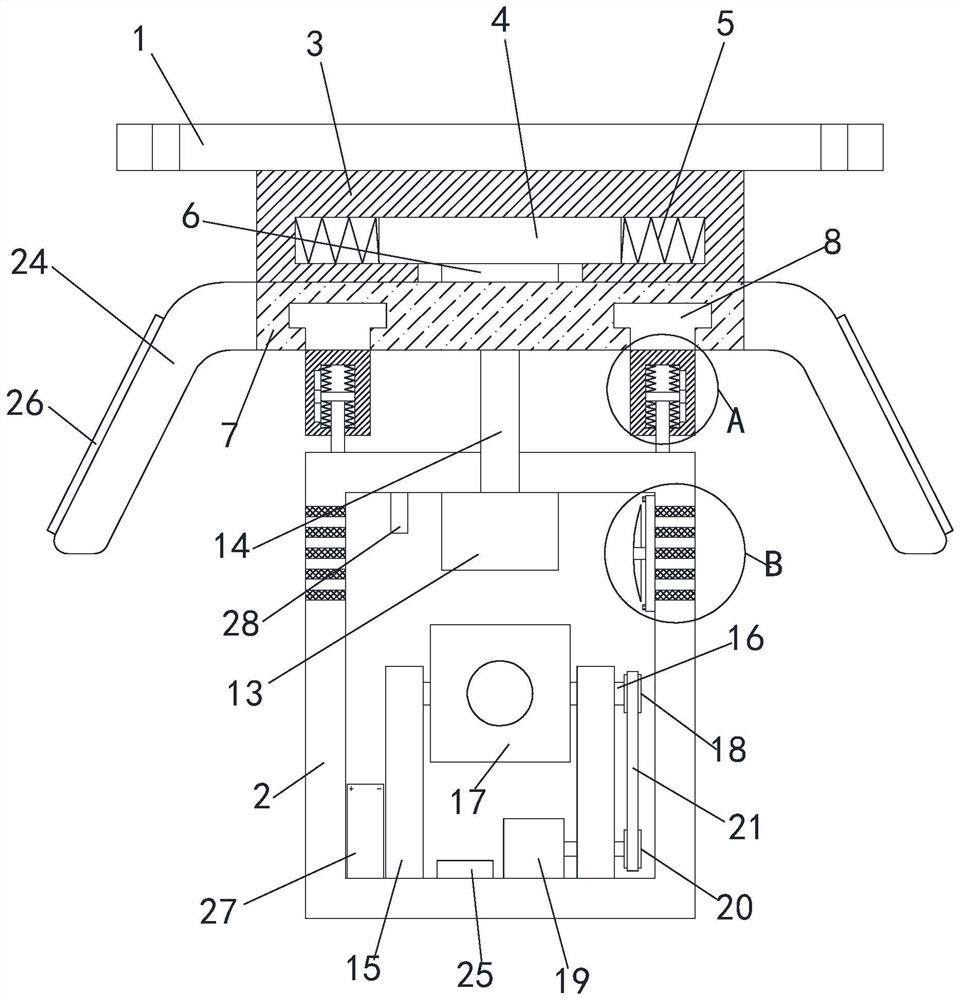
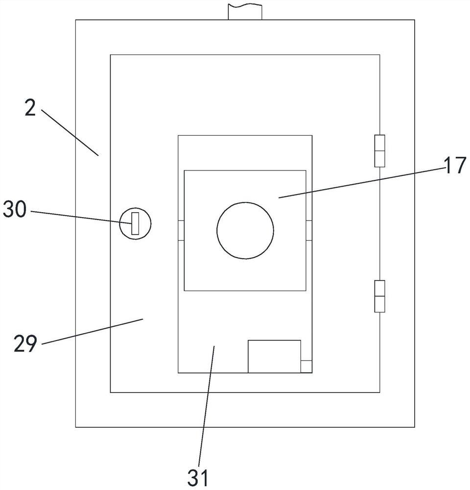
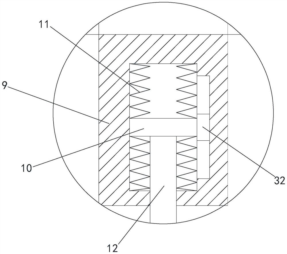
[0036] see Figure 1-4, a protective cover for monitoring equipment, including a mounting plate 1 and a protective shell 2, the bottom end of the mounting plate 1 is fixedly connected with a fixed block 3, the inside of the fixed block 3 is provided with a circular groove, and the inside of the circular groove is slidably provided with Circular plate 4, the outer side of circular plate 4 is evenly fixedly connected with a plurality of first springs 5, and one end of a plurality of first springs 5 ​​away from circular plate 4 is all fixedly connected with the inner sidewall of circular groove, in the circular groove groove of fixed block 3 A plurality of sensing components are arranged on the side of the inner wall facing the bottom of the circular plate 4, and the bottom end of the fixed block 3 is provided with a circular hole penetrating to the inside of the circular groove, and the bottom end of the circular plate 4 is fixedly connected with Fixed column 6, fixed column 6 i...


PUM


Abstract

The invention relates to the technical field of monitoring equipment, in particular to a protective cover of monitoring equipment and a protection method thereof. The protective cover comprises a mounting plate and a protective shell, a fixing block is fixedly connected to the bottom end of the mounting plate, a circular groove is formed in the fixing block, a circular plate is slidably arranged in the circular groove, and a plurality of first springs is evenly and fixedly connected to the outer side of the circular plate; the ends, away from the circular plate, of the multiple first springs are fixedly connected with the inner side wall of the circular groove, a circular hole penetrating into the circular groove is formed in the bottom end of the fixing block, a fixing column is fixedly connected to the bottom end of the circular plate and located in the circular hole, a connecting block is fixedly connected to the bottom end of the fixing column, and the top end of the connecting block is in sliding fit with the bottom end of the fixing block. A rotating groove is formed in the bottom end of the connecting block; the damping effect is improved, the device can be conveniently rotated, a filter screen can be prevented from being blocked, the heat dissipation effect of the device is improved, meanwhile, equipment in the protective shell can be conveniently detected and maintained, and the use practicability is improved.

Description

technical field [0001] The invention relates to the technical field of monitoring equipment, in particular to a protective cover for monitoring equipment and a protection method thereof. Background technique [0002] With the development of science and technology, monitoring equipment has become one of the important equipment in today's life and production. Most of the monitoring equipment is exposed to the outdoor environment, and it is easy to shorten the service life of the monitoring equipment due to wind and rain. [0003] After retrieval, the utility model patent with the Chinese patent number CN202020744509.8 discloses a protective cover for monitoring equipment, including a protective shell, and the left and right sides of the upper surface of the protective shell are connected with waterproof covers through connecting rods. , easy to repair and maintain, dustproof, waterproof and anti-collision, easy to adjust the angle, good heat dissipation effect. [0004] The a...

Claims


Application Information

Patent Timeline
Patent Type & Authority Applications(China)
IPC IPC(8): H04N5/225H04N5/232H04N7/18G03B17/55F16M11/12F16M11/18F16F15/067
CPCH04N7/18G03B17/55F16M11/12F16M11/18F16F15/067H04N23/51H04N23/695
Inventor 王丽
Owner 王丽
Why Eureka
Try Eureka