Mop cleaning barrel

A mop cleaning and water seat technology, which is applied in the field of mop cleaning buckets, can solve the problems of wasting water resources, wasting user labor, and high frequency of water changes, and achieve the effects of reducing labor costs, improving mopping efficiency, and ensuring reliability

Pending Publication Date: 2021-12-07
宁波德晶元电器有限公司
View PDF1 Cites 2 Cited by
  • Summary
  • Abstract
  • Description
  • Claims
  • Application Information

AI Technical Summary

Problems solved by technology

[0003] There are the following two problems in the current mop cleaning bucket: 1. Every time when using it, it is necessary to manually add water, or manually turn on the switch of the water tank, so that the clear water stored in the water tank is injected into the cleaning bucket, causing the user every time It is time-consuming and labor-intensive to use for the first time; 2. The cleaning bucket lacks a structure for separating clean sewage. The water in the cleaning bucket will become very dirty after one or two cleanings. Afterwards, the sewage in the cleaning bucket needs to be replaced first. After that, the mop can continue to be cleaned, and there is a problem that the frequency of water change is too high, which leads to a waste of user labor and a waste of water resources.
[0005] The above-mentioned cleaning bucket is used to clean the rotary mop, which is the same as the cleaning object in the present invention, but the above-mentioned cleaning bucket does not have the functions of water balance and separation of clean and sewage, and it needs to change the water several times during cleaning , which in turn leads to problems of wasting user labor and wasting water resources

Method used


Image

  • Mop cleaning barrel
  • Mop cleaning barrel
  • Mop cleaning barrel

Examples


Embodiment Construction

[0035] The following are specific embodiments of the present invention and in conjunction with the accompanying drawings, the technical method of the present invention is further described, but the present invention is not limited to these embodiments.

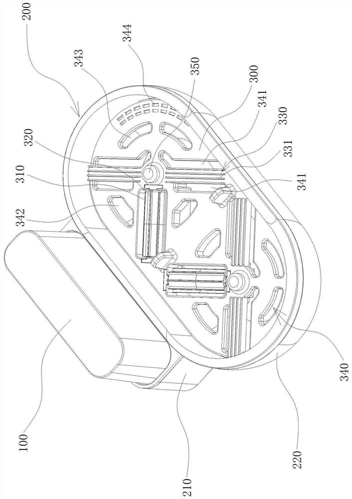
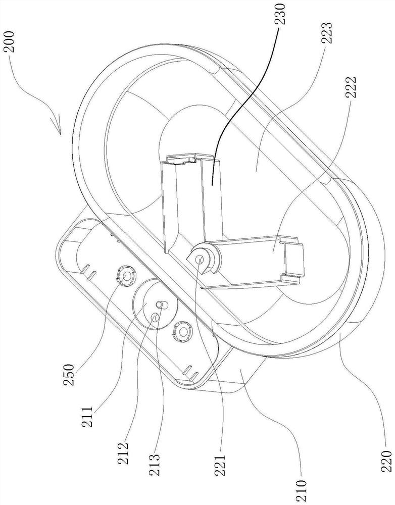
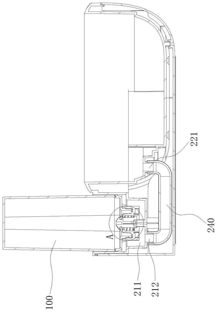
[0036] Such as Figure 1-6 As shown, the invention provides a mop cleaning bucket, comprising:

[0037] The water tank 100 has a water outlet channel 110 through which the water in the water tank 100 can flow out.

[0038] The cleaning barrel body 200 includes a water inlet seat 210 and a cleaning seat 220, the water inlet seat 210 is connected to the cleaning seat 220, the water inlet seat 210 is provided with a water storage chamber 211 and a water outlet 212, and the water outlet 212 is located in the water storage chamber 211 The water tank 100 is installed on the water inlet seat 210 and the water outlet channel 110 communicates with the water outlet 212. The cleaning seat 220 is provided with a water inlet 221, a clean ...


PUM


Abstract

The invention discloses a mop cleaning barrel, and belongs to the technical field of cleaning devices. The mop cleaning barrel comprises a water tank with a water outlet channel; a cleaning barrel body, which comprises a water inlet seat and a cleaning seat, wherein the water inlet seat is connected with the cleaning seat, the water inlet seat is provided with a water storage cavity and a water outlet, the water outlet is located in the water storage cavity, the water tank is installed on the water inlet seat, a water outlet channel is communicated with the water outlet, the cleaning seat is provided with a water inlet, a clean water cavity and a sewage cavity, the clean water cavity is separated from the sewage cavity, and the water inlet is formed in the clean water cavity and is communicated with the water outlet through a connecting pipeline; and a cleaning disc, which is provided with an impeller cavity, an impeller, a water scraping part and a drainage part, wherein the impeller cavity and the clean water cavity are arranged up and down, the impeller is rotatably arranged in the impeller cavity, and the water scraping part and the drainage part are both located above the sewage cavity. The cleaning barrel body has the functions of dynamic water balance and clean water and sewage separation, water does not need to be added repeatedly when the mop is cleaned every time, water does not need to be changed many times, the mopping efficiency is improved, and water resources are saved.

Description

technical field [0001] The invention belongs to the technical field of cleaning devices, and in particular relates to a mop cleaning bucket. Background technique [0002] The mop bucket is an important tool for household cleaning. Many mops are equipped with a corresponding cleaning bucket. After each mopping, you only need to put the mop into the cleaning bucket to quickly clean the mop. [0003] There are the following two problems in the current mop cleaning bucket: 1. Every time when using it, it is necessary to manually add water, or manually turn on the switch of the water tank, so that the clear water stored in the water tank is injected into the cleaning bucket, causing the user every time It is time-consuming and labor-intensive to use for the first time; 2. The cleaning bucket lacks a structure for separating clean sewage. The water in the cleaning bucket will become very dirty after one or two cleanings. Afterwards, the sewage in the cleaning bucket needs to be re...

Claims


Application Information

Patent Timeline
Patent Type & Authority Applications(China)
IPC IPC(8): A47L13/59
CPCA47L13/59
Inventor 薛胜利
Owner 宁波德晶元电器有限公司
Why Eureka
Try Eureka