Local heating method and system used after storage battery dispensing and cover closing

A technology of local heating and gluing cover, applied in the field of local heating and heating after the battery is glued and glued, it can solve the problems of large loss and low heat utilization efficiency, and achieve the effect of increasing the speed, avoiding heat loss and improving the utilization rate.

Pending Publication Date: 2021-12-07
ZHUZHOU YINGDING AUTOMATION EQUIP TECH
View PDF3 Cites 0 Cited by
  • Summary
  • Abstract
  • Description
  • Claims
  • Application Information

AI Technical Summary

Problems solved by technology

[0005] The present invention aims at the problem of low heat usage efficiency and excessive loss of heat during the heating and curing process of the current battery after gluing and covering, and proposes a local heating method and system for the battery after gluing and covering, placing the heat source close to the battery cover Heating, greatly reducing heat loss and saving energy

Method used


Image

  • Local heating method and system used after storage battery dispensing and cover closing
  • Local heating method and system used after storage battery dispensing and cover closing
  • Local heating method and system used after storage battery dispensing and cover closing

Examples


Embodiment 1

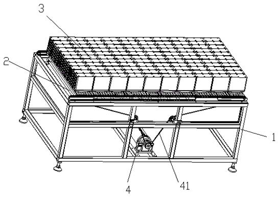
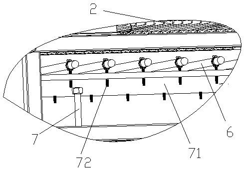
[0038] like figure 1 Shown, spot gluing A battery cover after local heating system, includes a frame 1, in this embodiment, the frame 1 as a whole has a rectangular parallelepiped configuration, with a conveying plate 2 is provided on a surface of the cuboid structure, spot gluing cap after the battery 3 is moved from one end of the conveying plate 2 to the other end of the conveying plate 2. like figure 2 , The heat source 2 is provided below the transfer plate 6, a plurality of heating pipes in the embodiment, the heat source 6 is arranged to the conveying direction of the plate width 2 of the present embodiment, equally spaced laying underneath the transport plate 2, and the conveying plate 2 to be covered baked cell 3 corresponding to the entire surface of the bottom, while ensuring entering the baking zone of the entire row of cells 3 heat evenly, glue substantially the same clotting time in the battery cover. A rack positioned on the transport plate portion 2 is provided bel...

Embodiment 2

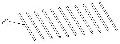
[0042] This embodiment substantially the same preceding embodiments, except that, as Figure 4 , The upper plate 2 transport structure 3 supporting the battery manner using support rods 22 and the connecting strip 23, the width direction of the plurality of support rods 22 disposed along the conveying plate 2, the connection between two adjacent support bars 22 using bar 23 is connected, at this time, the conveying plate has an annular structure 2 as a whole, 2 the overall movement of the motor 4 driven endless conveyor plate 3 relative to stimulate cell proceeds. The conveying motor 4 is connected between the plate 2 and the frame 1 and the transport connection between the plate 2 may be employed in a conventional manner. In this configuration, the connecting bar 23 requires the use of insulating materials or heat insulating material covering the contact portion 23 on the connector strip and the battery 4.

Embodiment 3

[0044] This embodiment according to the second embodiment substantially the same, except that, as Figure 5 As shown in this example embodiment of the support rod 22 by pairwise connecting structure, each of the two support rods 23 connected by a connecting bar 22, in this embodiment, the connecting bar 23 is disposed below the support rod 22, in which case , the battery on the contact surface portion 23 of the connecting bar 3 must be a thermal insulator, such Image 6 Shown, may be employed on the metal surface of the insulating layer structure of the sleeved. The support rod 22 is connected to the frame 1 may be employed in a conventional manner, such as connection hole 25 provided at both ends of the support rod 22 by a chain 22 connected to all the support rod 41 is provided with the connecting hole 25. Of course, the strength of the support rod 22 is sufficiently large, the connecting bar 23 can be canceled. Alternatively, each support rod 22 is provided individually, the conn...


PUM


Abstract

The invention relates to a local heating method and system used after storage battery dispensing and cover closing. To-be-baked parts of batteries are locally directly baked in a manner of arranging electric heating sources with openings being upward at the position below a conveying plate for containing the batteries, it is guaranteed that heat is transmitted to the to-be-baked parts of the batteries as much as possible in a manner of forming heat dissipation holes in the conveying plate, and meanwhile high-temperature-resistant heat insulation layers are arranged on the parts, making contact with the batteries, of the conveying plate to prevent the batteries from being burnt. By means of the manner, the structure is very simple, maintenance is convenient, heat can be transmitted to the batteries as much as possible, heat losses are greatly reduced, the heat utilization rate is increased, and energy consumption is reduced.

Description

Technical field [0001] The present invention relates to a method and a heating system, particularly relates to a method and system for locally heating the cover to a battery spot gluing, it belongs to the technical field of manufacturing the battery. Background technique [0002] In the production process of the battery, the battery case will need to spray glue in the groove undercut of the battery cover to the battery lid, and then heated to glue solidified, the battery is formed integrally. Most of the structures are present in a larger space, the heat from the top or side entry, the upper portion of the inner space of the low temperature throughout a large portion compete temperature, and the entire battery is fixed upside down on the bottom of the object, resulting in baking and drying the battery required temperature is difficult to rise up portion, thus wasting a lot of heat. The Application No. CN200820040493.1, entitled "battery cover sealants for rapid curing oven" and a...

Claims


Application Information

Patent Timeline
Patent Type & Authority Applications(China)
IPC IPC(8): B05D3/02B65G17/06H01M10/04
CPCB05D3/0254B65G17/063H01M10/0404Y02P70/50
Inventor 郑圣泉黎派龙
Owner ZHUZHOU YINGDING AUTOMATION EQUIP TECH
Why Eureka
Try Eureka