
Vibrating sand screening device for 3D printing

A 3D printing and vibrating device technology, applied in the fields of sieves, solid separation, chemical instruments and methods, etc., can solve problems such as screening blind areas, enhance the screening effect, reduce screening dead angles, and avoid inelastic deformation. Effect

Pending Publication Date: 2021-12-07
康硕(德阳)智能制造有限公司
View PDF13 Cites 0 Cited by
  • Summary
  • Abstract
  • Description
  • Claims
  • Application Information

AI Technical Summary

Problems solved by technology

[0007] In order to solve the problem that the vibrating screening device in the prior art can only use one vibration trajectory for screening at the same time, resulting in screening blind spots, a vibrating sand screening device for 3D printing is provided.

Method used


Image

  • Vibrating sand screening device for 3D printing
  • Vibrating sand screening device for 3D printing

Examples


Embodiment 1

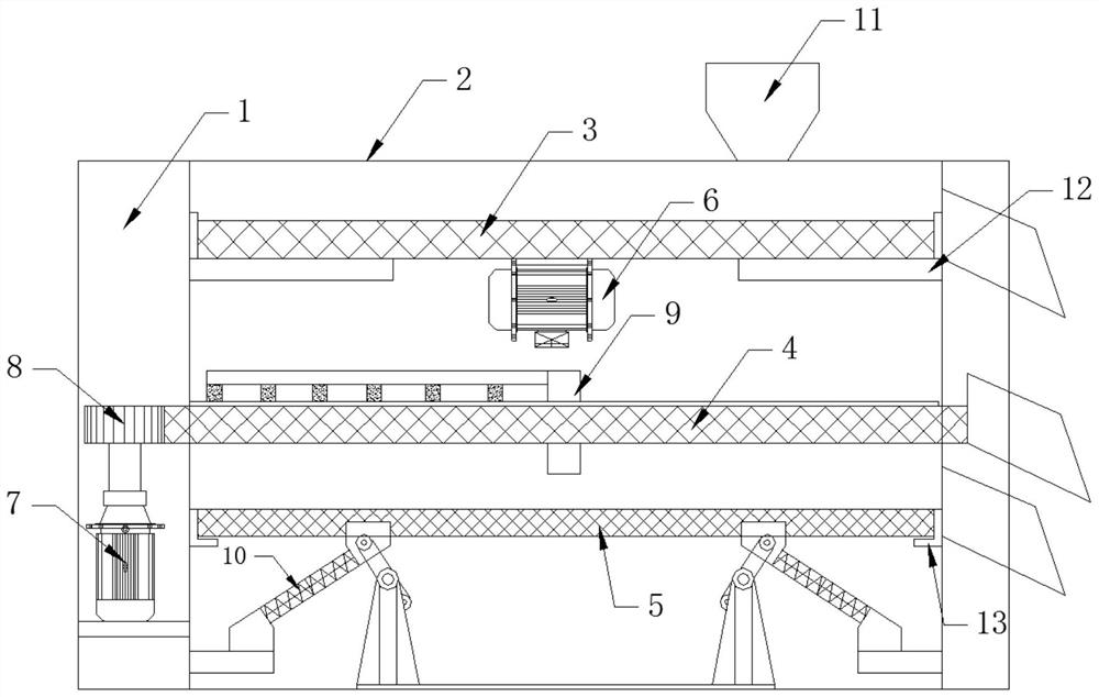
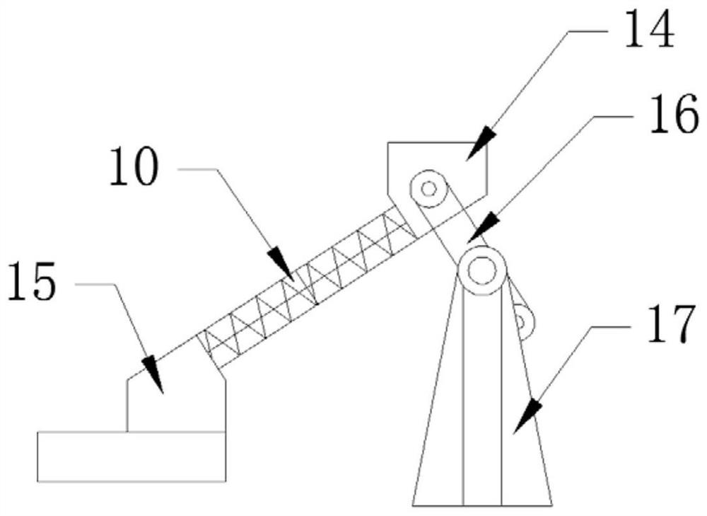
[0024] A vibrating sand screening device for 3D printing, comprising a frame 1, the periphery of the frame 1 is connected with an organic casing 2, and the frame 1 is sequentially installed with a primary sieve plate 3, a secondary sieve plate 4 and a third sieve plate from top to bottom. The first-stage sieve plate 5, the first-stage sieve plate 3 is connected with a vibrating motor 6, the side of the second-stage sieve plate 4 is provided with meshing teeth, and a rotating motor 7 is installed in the frame 1, and the rotating motor 7 is connected with a driving gear 8, and the driving gear 8 cooperates with the meshing teeth, and a rolling device 9 is installed on the secondary sieve plate 4, and a reciprocating vibration device is connected to the bottom of the third-stage sieve plate 5. The direction is inclined to the horizontal plane, and the vibrating spring 10 is connected with a driving device. The size of the sieve holes on the third-stage sieve plate 5 is smaller tha...

Embodiment 2

[0027] On the basis of Embodiment 1, the rolling device 9 includes a fixed shaft, the fixed shaft is fixedly connected to the frame 1, a bearing is connected between the secondary sieve plate 4 and the fixed shaft, and a roller connecting frame is connected to the upper end of the fixed shaft. A plurality of rollers are installed on the wheel connecting frame.

[0028] The relative motion structure of the rotating sieve plate and the stationary grinding wheel uses the principle of centrifugal force to overcome the problem that the grinding wheel can only act on the sand on the path of the grinding wheel when the grinding wheel rotates. The bottom moves gradually from the center of the sieve plate to the periphery of the sieve plate, and evenly contacts with the roller.

Embodiment 3

[0030] On the basis of Embodiment 1, the bottom of the primary sieve plate 3 is connected with a support plate 12, the support plate 12 is connected with the frame 1, and the sides of the primary sieve plate 3 and the third stage sieve plate 5 are connected with the frame 1 Flexible support block 13 is arranged. Through the cooperation of the support plate 12 and the flexible support block 13, the sand material can be prevented from leaking downward from the side while meeting the vibration space requirement of the sieve plate, and the unscreened sand material can be prevented from falling into the next-level screening mechanism to realize sealing.


PUM


Abstract

The invention discloses a vibrating sand screening device for 3D printing, belongs to the technical field of 3D printing corollary equipment, and solves the problem that a vibrating sand screening device in the prior art has a screening blind area. The vibrating sand screening device for 3D printing comprises a rack; the periphery of the rack is connected with a machine shell; the rack is sequentially provided with a first-stage screening plate, a second-stage screening plate and a third-stage screening plate from top to bottom; the first-stage screening plate is connected with a vibration motor; meshing teeth are arranged on the side face of the second-stage sieve plate; a rotating motor is installed in the rack; the rotating motor is connected with a driving gear; the driving gear is matched with the meshing teeth; a rolling device is installed on the second-stage screening plate; a reciprocating vibration device is connected to the bottom of the third-stage screening plate; the reciprocating vibration device comprises a group of symmetrically arranged vibration springs; the vibration direction of the vibration springs is inclined to the horizontal plane; and the vibration springs are connected with a driving device. The vibrating sand screening device for 3D printing is used for screening the sand for the sand mold 3D printer; and the screened sand is high in consistency.

Description

technical field [0001] The invention belongs to the technical field of 3D printing supporting equipment, and in particular relates to a vibrating sand screening device for 3D printing. Background technique [0002] 3D printing technology, also known as "additive manufacturing" technology, is a cutting-edge technology that requires the close cooperation of materials science technology, electromechanical control technology, information technology and other technologies, involving CAD modeling, machinery, laser and materials, etc. Multiple subjects, with the help of 3D model data, are printed from bottom to top. [0003] The 3D printer is equipped with different "printing materials" such as metal, ceramics, plastics, sand, etc. After the printer is connected to the computer, the "printing materials" can be superimposed layer by layer through computer control, and finally the blueprint on the computer can be turned into a real object. Therefore, a 3D printer is a device that ca...

Claims


Application Information

Patent Timeline
Patent Type & Authority Applications(China)
IPC IPC(8): B07B1/28B07B1/42B07B1/46
CPCB07B1/28B07B1/42B07B1/46B07B1/4663B07B2201/04
Inventor 刘江博闻段戈扬陈彬
Owner 康硕(德阳)智能制造有限公司
Learn More