
Rubber cutting device

A cutting device and rubber technology, used in metal processing, non-rotational vibration suppression, etc., can solve problems such as operator injury, insufficient cutting surface, rubber residue, etc., to avoid rigid contact, reduce safety hazards, and reduce wear effects.

Pending Publication Date: 2021-12-07
王清平
View PDF0 Cites 1 Cited by
  • Summary
  • Abstract
  • Description
  • Claims
  • Application Information

AI Technical Summary

Problems solved by technology

[0003] At present, the production process of rubber products is mostly to cut rubber before rubber refining, so that large rubber sheets become small rubber strips, so that it is easy to prepare for extrusion of rubber in the next process, but the existing rubber cutting opportunities Because of the characteristics of the rubber itself, the ejection occurs, especially when the elastic rubber such as natural rubber is cut and ejected with a very strong force, it will cause harm to the operator after the ejection, and the rubber is sticky, there will be Rubber remains on the cutting knife, which will affect the subsequent rubber cutting, resulting in uneven cutting surface and affecting the service life of the cutting knife. Therefore, we propose a rubber cutting device to solve the above problems

Method used


Image

  • Rubber cutting device
  • Rubber cutting device
  • Rubber cutting device

Examples


Embodiment Construction

[0026] The technical solutions in the embodiments of the present invention will be clearly and completely described below with reference to the accompanying drawings in the embodiments of the present invention. Obviously, the described embodiments are only a part of the embodiments of the present invention, but not all of the embodiments. Based on the embodiments of the present invention, all other embodiments obtained by those of ordinary skill in the art without creative efforts shall fall within the protection scope of the present invention.

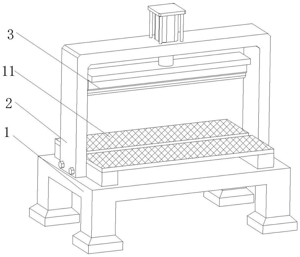
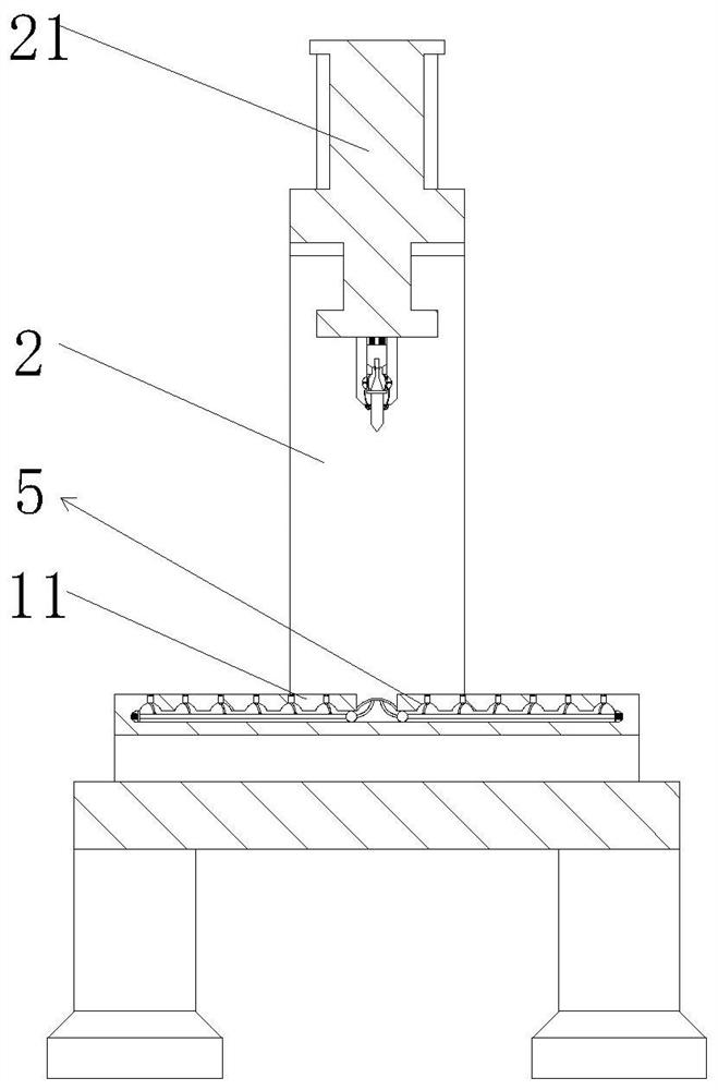
[0027] see Figure 1-7 , The present invention provides a technical solution: a rubber cutting device, comprising a workbench 1, a plurality of support legs are fixedly connected to the bottom of the workbench 1, and a non-slip base is fixedly connected to the bottom of the support legs, and the workbench 1 is fixedly installed with a limited position Plate 11, a support frame 2 is fixedly installed at both ends of the limit plate 11,...


PUM


Abstract

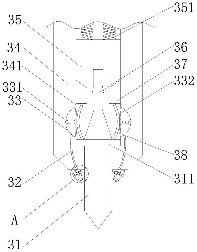
The invention discloses a rubber cutting device. The rubber cutting device comprises a workbench, a plurality of supporting legs are fixedly connected to the bottom of the workbench, anti-skid bases are fixedly connected to the bottoms of the supporting legs, a limiting plate is fixedly installed on the workbench, supporting frames are fixedly installed at the two ends of the limiting plate, the supporting frames are fixedly installed on the workbench, and air cylinders are fixedly installed on the supporting frames. The bottoms of the cylinders are fixedly connected with a driving rod, and the bottom of the driving rod is fixedly connected with a cutting mechanism. Compared with the prior art, a cutting knife abuts against a buffer plate, the cutting knife retracts inwards, the cutting knife retracts to drive a connecting plate to move inwards, an arc-shaped plate pair deforms, the arc-shaped plate extrudes an elastic film, gas in an air pressure cavity is conveyed into a cleaning cavity through a connecting pipeline, and an elastic plate can deform; and a scraper blade is pushed to move outwards, one end of the scraper blade can abut against the surface of the cutting knife, and residual rubber on the surface of the cutting knife can be scraped off in the retracting process of the cutting knife and is prevented from being accumulated on the surface of the cutting knife.

Description

technical field [0001] The invention relates to the technical field of rubber machinery, in particular to a rubber cutting device. Background technique [0002] Rubber refers to a highly elastic polymer material with reversible deformation, which is elastic at room temperature, can produce large deformation under the action of a small external force, and can return to its original shape after removing the external force. [0003] At present, most of the production processes of rubber products are to cut the rubber before rubber refining, so that the large rubber sheet becomes small rubber strips, so that it is easy to prepare for the extrusion of rubber in the next process, but the existing rubber cutting opportunities Due to the characteristics of the rubber itself, the ejection occurs, especially for the elastic rubber such as natural rubber, the cutting and ejection force is very strong, which will cause harm to the operator after ejection. The rubber remains on the cutt...

Claims


Application Information

Patent Timeline
IPC IPC(8): B26D1/06B26D5/12B26D7/08B26D7/22B26D7/02B26D7/01B26D7/18F16F15/02
CPCB26D1/06B26D5/12B26D7/088B26D7/22B26D7/02B26D7/015B26D7/18F16F15/02
Inventor 王清平
Owner 王清平
Learn More