Multifunctional intelligent door lock clutch switch structure

A technology of intelligent door lock and switch structure, which is applied to building locks, building structures, locks operated by non-mechanical transmission, etc., can solve the problems of high manufacturing cost of clutches, avoid toothing of gear components, solve slow unlocking, and avoid The effect of too many parts

Pending Publication Date: 2021-12-07
东莞市立群智能科技有限公司
View PDF0 Cites 0 Cited by
  • Summary
  • Abstract
  • Description
  • Claims
  • Application Information

AI Technical Summary

Problems solved by technology

[0005] In order to solve the above-mentioned problem of high manufacturing cost of the intelligent door lock clutch in the prior art, this solution provides a clutch switch structure of a multifunctional intelligent door lock

Method used


Image

  • Multifunctional intelligent door lock clutch switch structure
  • Multifunctional intelligent door lock clutch switch structure
  • Multifunctional intelligent door lock clutch switch structure

Examples


Embodiment 1

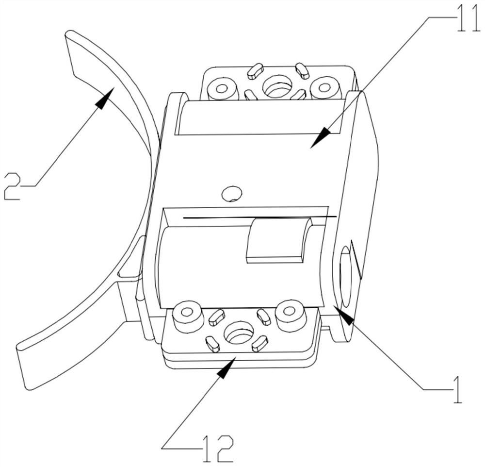
[0033] Such as Figure 1 to Figure 3 As shown, in this embodiment, a clutch switch structure of a multifunctional intelligent door lock is designed, including structures such as a fixed housing base 1, a power mechanism, a thrust assembly 5, and a curved push piece 2.

[0034] The fixed housing base 1 is in the shape of a square box, and in the fixed housing base 1, there are chute, motor installation slot, gear installation slot and manual control slot. A front wall plate and a rear wall plate are respectively arranged at two ends of the chute, and the U-shaped guide part 24 slides between the front wall plate and the rear wall plate. The motor installation slot is arranged on the left side of the chute, the gear installation slot is arranged at the end of the chute, and the manual control slot is arranged on the right side of the chute. Both left and right sides of the fixed shell base 1 are provided with connecting ears 12 with holes, through which the fixed shell base 1 c...

Embodiment 2

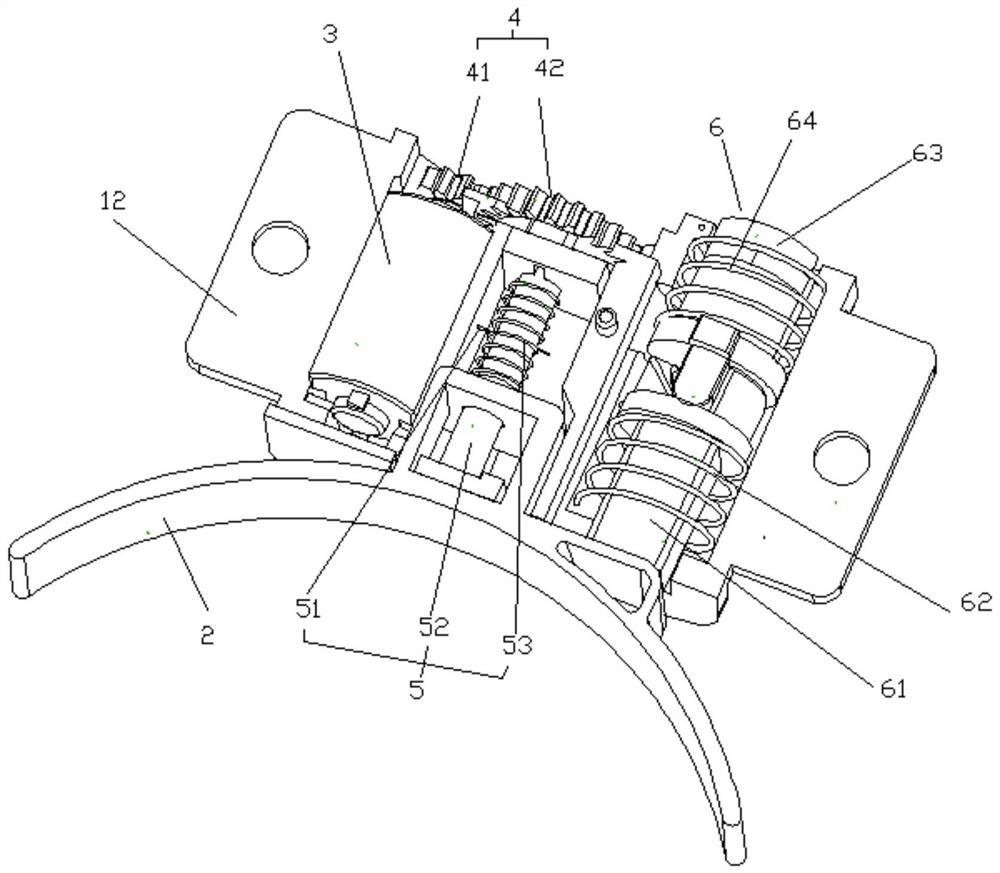
[0040] Such as Figure 1 to Figure 3 As shown, this embodiment designs a clutch switch structure of a multifunctional intelligent door lock, including a fixed housing 1, a power mechanism, a thrust assembly 5, a manual control assembly 6 and a curved pusher 2 and other components.

[0041] A chute and a manual control slot are arranged in the fixed housing 1, and a front wall and a rear wall are respectively arranged at both ends of the chute, and the U-shaped guide part 24 is located between the front wall and the rear wall. slide between. An upper case cover 11 is arranged on the fixed case base 1 .

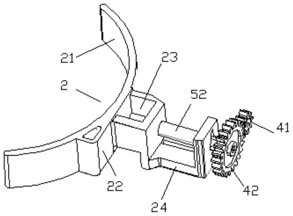
[0042] The curved surface pusher 2 includes a U-shaped guide part 24 and a curved surface clutch part 21. The curved surface clutch part 21 is arc-shaped and is located outside the fixed housing 1; the U-shaped guide part 24 is connected to the back side of the curved surface clutch part 21. The U-shaped guide part 24 is slidably installed in the chute; when the U-shaped guid...


PUM


Abstract

The invention belongs to the technical field of clutches of intelligent door locks, and particularly relates to a multifunctional intelligent door lock clutch switch structure. The structure comprises a fixed shell seat as well as a power mechanism, a thrust component, a manual control component and other components integrated on the fixed shell seat, so that the integration level of the clutch switch structure can be increased, and the manufacturing cost of a clutch switch is reduced. In two springs of the manual control component, the elastic force of the protection spring is larger than that of the return spring, so that in the process that a driving motor controls a curved-surface pushing piece to retract, the protection spring can provide certain buffering, and the phenomenon that a gear assembly breaks teeth or the load of the driving motor is increased due to the fact that the curved-surface pushing piece stops suddenly is avoided; and according to the scheme, all parts are simplified, the problems of too many parts, tedious installation, difficult maintenance and the like are avoided, the problems that an existing clutch switch is slow in unlocking, serious in abrasion, high in power consumption and the like, and a motor is damaged are solved, and normal use in the use process is ensured.

Description

technical field [0001] The invention belongs to the technical field of clutches for intelligent door locks, and in particular relates to a clutch switch structure for multifunctional intelligent door locks. Background technique [0002] Smart lock is the executive component of locking the door in the access control system. With the advent of the intelligent era, smart household products, especially smart door locks, are used more and more in people's lives, and the fields are becoming more and more extensive. While ensuring the safety of people's property and life, smart locks also meet the requirements for humanization and intelligence. Different from traditional mechanical locks, smart locks are more intelligent in terms of user identification, security, and management. The smartness of smart locks is reflected in whether they can be remotely controlled by mobile phones and linked with smart homes. At present, on the market, various smart locks emerge in endlessly, each w...

Claims


Application Information

Patent Timeline
Patent Type & Authority Applications(China)
IPC IPC(8): E05B47/00E05B15/00E05B15/04E05B17/22
CPCE05B47/0012E05B15/00E05B15/04E05B17/22E05B2047/0026E05B2047/002E05B2015/0406E05B2015/0448
Inventor 孙家群
Owner 东莞市立群智能科技有限公司
Why Eureka
Try Eureka