Drilling device for mine engineering blasting

A drilling device and mining engineering technology, applied in drilling tools, directional drilling, earthwork drilling and mining, etc., can solve problems such as difficulty for construction personnel to stand firmly, reduce drilling rig efficiency, and increase construction personnel's operation difficulty, so as to improve construction safety , Improve the convenience of operation, good protection effect

Pending Publication Date: 2021-12-07
中国非金属材料南京矿山工程有限公司
View PDF0 Cites 2 Cited by
  • Summary
  • Abstract
  • Description
  • Claims
  • Application Information

AI Technical Summary

Problems solved by technology

Due to the complex topography of the mining face, it is impossible to use large-scale drilling equipment for construction; currently, blast drilling on the face of the mine is generally carried out with small drilling rigs, and construction personnel need to hold the small drilling rig at close range during operation. Avoid the drilling rig's own vibration to cause the hole to shift; during the drilling process, water and wind need to be sent through the drill pipe to the drill bit end to cool down, and at the same time, the debris generated by the drilling can be taken out of the hole to avoid blocking the hole and reducing the temperature. The efficiency of the drilling rig; however, the mud-water mixture derived from the hole will accumulate at the feet of the construction personnel along with the drill pipe, making it difficult for the construction personnel to stand firmly in areas with complex terrain and increase the difficulty of operation for the construction personnel; therefore, there is an urgent need for a Drilling device for mine engineering blasting with high construction safety

Method used


Image

  • Drilling device for mine engineering blasting
  • Drilling device for mine engineering blasting
  • Drilling device for mine engineering blasting

Examples


Embodiment 1

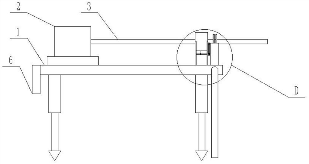
[0027] Such as figure 1 As shown, a drilling device for mine engineering blasting includes: a workbench 1, a motor 2, a drill rod 3, and a collection assembly; the motor 2 is arranged on the workbench 1, and the motor 2 and the workbench 1 pass through the guide assembly sliding connection; the drill rod 3 is horizontally arranged above the workbench 1, and the drill rod 3 is connected to the output shaft of the motor 2 for drilling; the collection assembly is arranged at the end of the drill rod 3 away from the motor 2, It is used to collect the mud-water mixture brought out by the drill pipe 3 from the hole; the mud-water mixture brought out by the drill pipe can be collected centrally through the collection component, so as to avoid flowing to the ground and affect the safety of construction personnel;

[0028] The collection assembly includes: a support set on the workbench 1 and directly below the drill pipe 3, the support is connected to the workbench 1; On both sides, ...

Embodiment 2

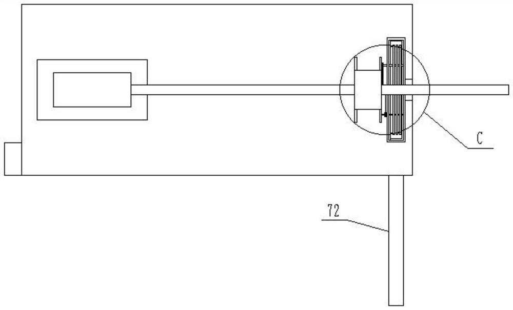
[0033] Such as Figure 5 As shown, in order to further improve the convenience of operation, the wind brought out by the drill pipe is used as the power through the annular air guide channel to drive the cleaning wheel to work and improve the utilization efficiency of resources; it can not only collect the mud-water mixture on the drill pipe, but also reduce the wind. Speed, to avoid the impact on people's glasses, to facilitate the observation of the drilling situation.

[0034] Preferably, the drive mechanism includes an inner tube 21 sleeved on the drill pipe 3 and coaxial with it, the outer side of the inner tube 21 is sleeved with an outer tube 22 and forms an annular air guide channel with it, the outer wall of the outer tube 22 and the bracket Connecting, on the annular air guide channel, a plurality of fan leaves 23 are evenly arranged radially with its axis as the center, and the outer wall of the inner tube 21 and the inner wall of the outer tube 22 are respectively ...

Embodiment 3

[0036] In order to further improve the collection efficiency of the mud-water mixture, pulleys and gears are used to make the cleaning wheels on both sides rotate to the side of the drill pipe to prevent the mud-water mixture from splashing outward.

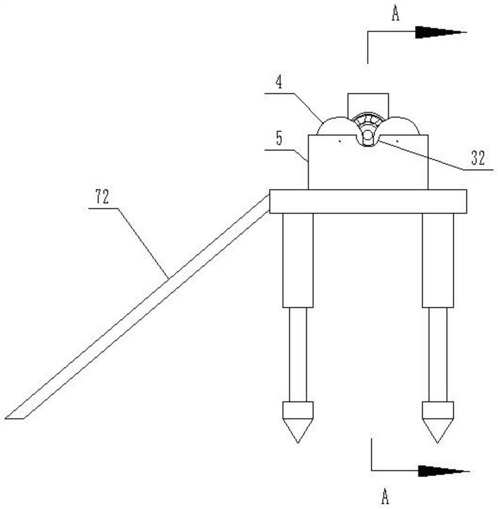
[0037] Such as figure 2 , 6 , 7, preferably, the bracket includes two first U-shaped support plates 31 arranged on the workbench 1, and the bottom of the outer tube 22 fits and fixes with the inner sides of the two first U-shaped support plates 31 respectively. connection, the bottom of the first U-shaped support plate 31 is vertically fixedly connected to the workbench 1, and the side of the collection bucket 5 away from the workbench 1 is provided with an arc-shaped groove 32 and is located directly below the drill pipe 3. The arc-shaped groove 32 Two first rotating shafts 33 are arranged symmetrically on both sides of the shaft and are parallel to the drill pipe 3. The two ends of the first rotating shaft 33 are connected to...


PUM


Abstract

The invention relates to a drilling device for mine engineering blasting, and belongs to the technical field of mining equipment. The drilling device comprises a workbench, a motor, a drill rod and a collecting assembly. The motor is arranged on the workbench, the drill rod is horizontally arranged above the workbench, and the drill rod is connected with the output shaft of the motor and used for drilling; the collecting assembly is arranged at the end, away from the motor, of the drill rod and used for collecting a mud-water mixture brought out of a hole by the drill rod; the collecting assembly comprises a support and a plurality of cleaning wheels. The support is arranged on the workbench and located under the drill rod; the multiple cleaning wheels are uniformly and symmetrically arranged on the support and are positioned on the two sides of the drill rod. According to the drilling device for mine engineering blasting, the mud-water mixture brought out by the drill rod can be collected in a centralized mode through the collecting assembly, and it is avoided that the mud-water mixture flows to the ground, and the safety of constructors is affected; the mud-water mixture on the drill rod is cleaned down in advance through a cleaning wheel, so that the mud-water mixture is prevented from being splashed to an operator, and the construction safety is improved; the drilling device for mine engineering blasting is good in protection effect, easy to operate, high in practicability and worthy of popularization.

Description

technical field [0001] The invention belongs to the technical field of mining equipment, and in particular relates to a drilling device for blasting in mine engineering. Background technique [0002] When mining a mine, blasting means are usually used to blast the ore, so as to facilitate the collection of ore. In order to improve the blasting efficiency, it is usually necessary to drill holes on the face of the tunnel before blasting, and then install explosives in the holes for blasting. Due to the complex topography of the mining face, it is impossible to use large-scale drilling equipment for construction; currently, blast drilling on the face of the mine is generally carried out with small drilling rigs, and construction personnel need to hold the small drilling rig at close range during operation. Avoid the drilling rig's own vibration to cause the hole to shift; during the drilling process, water and wind need to be sent through the drill pipe to the drill bit end to...

Claims


Application Information

Patent Timeline
Patent Type & Authority Applications(China)
IPC IPC(8): E21B7/04E21B12/06E21B21/00E21B21/06
CPCE21B7/04E21B21/00E21B12/06E21B21/065
Inventor 方宏张勋刘轶伦蒋传磊王聪田磊陈思豪高立峰张正修于际军黄楠李楠袁丁郑力嘉顾阳光耿兴玉王站张干臣李松杨士汉刘淼朱玉倩梁婷婷王延富张光华王强方之航
Owner 中国非金属材料南京矿山工程有限公司
Why Eureka
Try Eureka