Low-cavitation parallel overflow valve

A technology of parallel connection and relief valve, applied in the field of hydraulic valves, can solve problems such as poor cavitation suppression effect, cavitation jet flow, pressure pulsation, etc., and achieve the effect of simple structure, reduced cavitation intensity, and large flow capacity

Active Publication Date: 2021-12-07
ZHAOQING UNIV
View PDF9 Cites 0 Cited by
  • Summary
  • Abstract
  • Description
  • Claims
  • Application Information

AI Technical Summary

Problems solved by technology

During the operation of the system, because the relief valve needs to bear extremely high pressure difference, it is easy to form cavitation jet phenomenon downstream of the throttle port, resulting in adverse effects such as cavitation, noise, pressure pulsation, etc.
The traditional overflow valve mainly improves the cavitation suppression ability by delaying the formation of cavitation, and its cavitation suppression effect is not good under the condition of high-intensity cavitation flow

Method used


Image

  • Low-cavitation parallel overflow valve
  • Low-cavitation parallel overflow valve
  • Low-cavitation parallel overflow valve

Examples


Embodiment Construction

[0016] The technical solutions of the present invention will be further described below in conjunction with the accompanying drawings and through specific implementation methods.

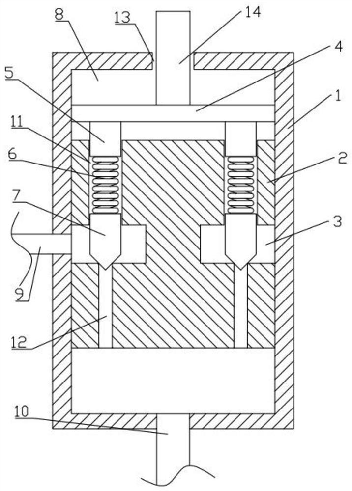
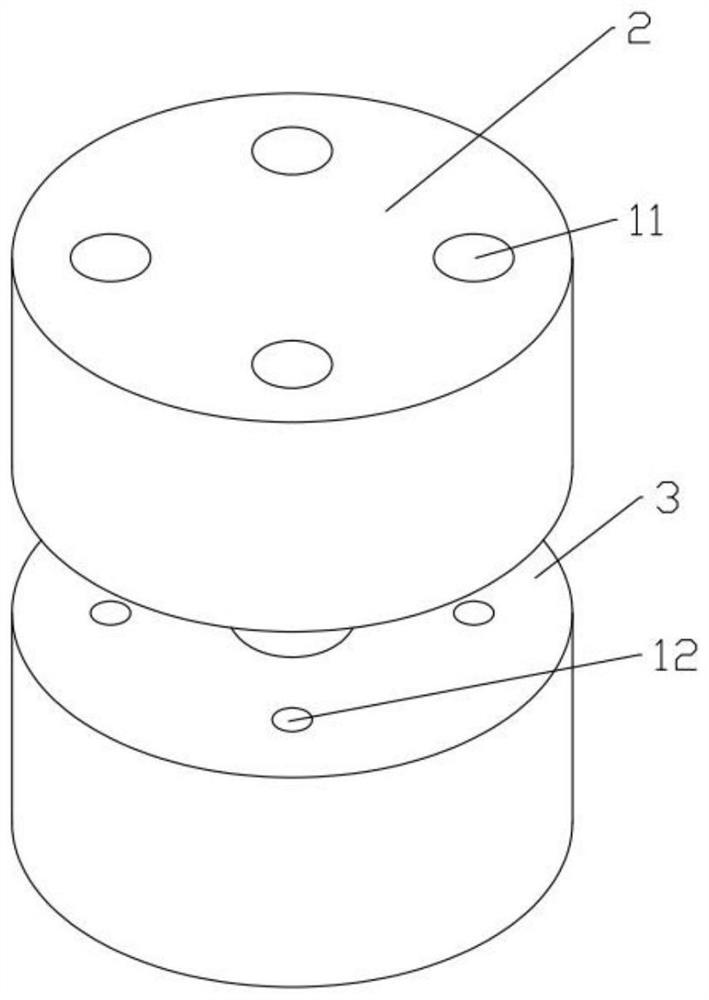
[0017] Such as Figure 1-3 As shown, the embodiment provides a low-cavitation parallel relief valve, including a valve body 1, a valve sleeve 2, a top plate 4, a plunger 5, a compression spring 6 and a conical valve core 7, and the valve body 1 is set There is an oil delivery chamber 8, the valve sleeve 2 is fixed in the oil delivery chamber 8, the side of the valve sleeve 2 is provided with a ring groove 3, and the top of the valve sleeve 2 is provided with more than two first through holes 11, the first through holes 11 are connected with the ring The groove 3 is connected, the conical valve core 7 is slidably connected in the first through hole 11, the top plate 4 is set above the valve sleeve 2, and the top plate 4 is slidably connected with the oil delivery chamber 8, and more than two plungers...


PUM


Abstract

The invention discloses a low-altitude parallel overflow valve. An oil conveying cavity is formed in a valve body, a valve sleeve is fixedly arranged in the oil conveying cavity, an annular groove is formed in the side face of the valve sleeve, two or more first through holes are formed in the top of the valve sleeve, the first through holes are communicated with the annular groove, conical valve elements are slidably connected into the first through holes, and a top plate is arranged above the valve sleeve. The top plate is slidably connected with the oil conveying cavity, two or more plungers are fixedly arranged at the bottom of the top plate, the plungers are inserted into the first through holes, compression springs abut against the portions between the conical valve elements and the plungers, second through holes are formed in the bottom of the valve sleeve and communicated with the annular groove, and the conical valve elements abut against the second through holes. An oil outlet communicated with the annular groove is formed in one side of the valve body, and an oil inlet communicated with the oil conveying cavity is formed in the bottom of the valve body. The multiple conical valve elements are arranged in parallel, so that the increase of vortex cavitation can be inhibited, the cavitation intensity can be remarkably reduced under the high-intensity cavitation flow condition, and meanwhile it can be guaranteed that the overflow valve has the large flow capacity.

Description

technical field [0001] The invention relates to the technical field of hydraulic valves, in particular to a low-cavitation parallel relief valve. Background technique [0002] Relief valves are common hydraulic components used to maintain constant system pressure. During the operation of the system, since the relief valve needs to bear extremely high pressure difference, it is easy to form a cavitation jet phenomenon downstream of the orifice, resulting in adverse effects such as cavitation, noise, and pressure pulsation. The traditional overflow valve mainly improves cavitation suppression ability by delaying cavitation initiation, but its cavitation suppression effect is not good under high-intensity cavitation flow conditions. Contents of the invention [0003] In order to overcome the defects of the prior art, the technical problem to be solved by the present invention is to propose a low-cavitation parallel overflow valve. By setting a plurality of conical valve core...

Claims


Application Information

Patent Timeline
Patent Type & Authority Applications(China)
IPC IPC(8): F16K17/06F16K1/44F16K1/38F16K27/02F16K47/02
CPCF16K17/06F16K17/044F16K17/0473F16K1/44F16K1/38F16K27/0254F16K47/02Y02E10/20
Inventor 袁聪朱丽莎李焕军李鹤王悦勇杜尊令
Owner ZHAOQING UNIV
Why Eureka
Try Eureka