Microwave vacuum freeze-drying device
A microwave vacuum and vacuuming device technology, applied in the field of microwave applications, can solve the problems of continuous batch processing, insufficient heating and drying uniformity of frozen materials, etc., and achieve the effects of good shape retention, less component loss, and uniform drying of materials
- Summary
- Abstract
- Description
- Claims
- Application Information
AI Technical Summary
Problems solved by technology
Method used
Image
Examples
Embodiment 1
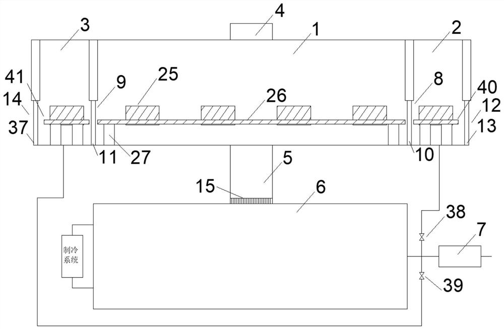
[0028] See attached figure 1 or 6. The microwave vacuum freeze-drying device includes a drying chamber 1, a front transition chamber 2, a rear transition chamber 3, a microwave input device 4, a material conveying device, a material storage device, a water and air channel 5, a cold trap 6 and a vacuuming device 7; The drying chamber 1 communicates with the cold trap 6 through the water-air channel 5; the cold trap 6 is connected with a vacuum device 7 through a pipeline; the drying chamber 1 is provided with a drying inlet 8 and a drying outlet 9; the drying chamber 1 The drying inlet 8 communicates with the front transition chamber 2, and the drying chamber 1 communicates with the rear transition chamber 3 through the drying outlet 9; the drying inlet 8 is provided with a first electric control door 10 that controls the opening and closing of the drying inlet 8; the drying The outlet 9 is provided with a second electric control door 11 that controls the opening and closing o...
Embodiment 2
[0030] See attached Figure 1~4 . On the basis of Embodiment 1, the third door 13 and the fourth door 37 are both electrically controlled doors; the pipeline connecting the front transition chamber 2 to the vacuum device 7 is provided with a first control valve 38; A second control valve 39 is provided on the pipeline connecting the transition chamber 3 to the vacuum device 7; a first conveying device 40 is provided in the front transition chamber 2; the first conveying device 40 is used to transfer the material storage device from the material inlet 12 is transported to the drying inlet 8; the rear transition chamber 3 is provided with a second conveying device 41; the second conveying device 41 is used to transport the material storage device from the drying outlet 9 to the material outlet 14. It can be seen from the above structure that the third door 13 and the fourth door 37 are all electric control doors, which can be automatically controlled by the controller; the firs...
Embodiment 3
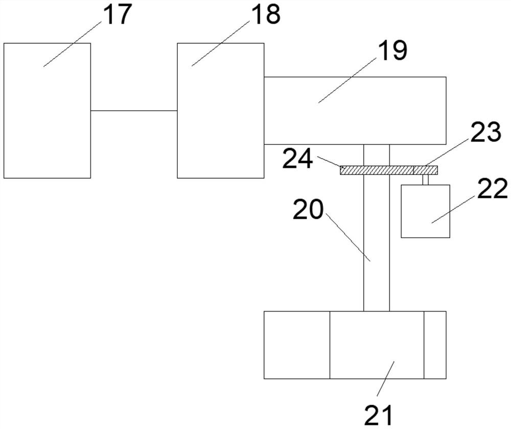
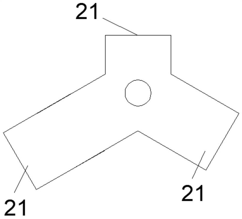
[0036] See attached Figure 2-6 . On the basis of Embodiment 1, the third door 13 and the fourth door 37 are both electrically controlled doors; the pipeline connecting the front transition chamber 2 to the vacuum device 7 is provided with a first control valve 38; A second control valve 39 is provided on the pipeline connecting the transition chamber 3 to the vacuum device 7; a first conveying device 40 is provided in the front transition chamber 2; the first conveying device 40 is used to transfer the material storage device from the material inlet 12 is transported to the drying inlet 8; the rear transition chamber 3 is provided with a second conveying device 41; the second conveying device 41 is used to transport the material storage device from the drying outlet 9 to the material outlet 14. It can be seen from the above structure that the third door 13 and the fourth door 37 are all electric control doors, which can be automatically controlled by the controller; the firs...
PUM
 Abstract
Description
Claims
Application Information
 - R&D
- Intellectual Property
- Life Sciences
- Materials
- Tech Scout
- Unparalleled Data Quality
- Higher Quality Content
- 60% Fewer Hallucinations
Browse by: Latest US Patents, China's latest patents, Technical Efficacy Thesaurus, Application Domain, Technology Topic, Popular Technical Reports.
© 2025 PatSnap. All rights reserved.Legal|Privacy policy|Modern Slavery Act Transparency Statement|Sitemap|About US| Contact US: help@patsnap.com


