Road surface state instrument control circuit

A technology for controlling circuits and road conditions, applied in the field of detection instruments, can solve the problems of inability to judge and remind, the camera can only take images, and the camera function discount, etc., to achieve the effect of convenient acquisition

Pending Publication Date: 2021-12-07
SHENZHEN LANSITENG TECH
View PDF5 Cites 0 Cited by
  • Summary
  • Abstract
  • Description
  • Claims
  • Application Information

AI Technical Summary

Problems solved by technology

[0002] With the development of science and technology, more and more detection instruments have been applied to people's lives. Road and traffic detection equipment has also been widely used beside vehicles and roads. Most vehicles now use cameras to collect road traffic information. , but the camera can only take images, and cannot judge and remind the roads of rain, snow, icing, etc. Various states still need people to judge, and the camera function will be greatly reduced when it is dark

Method used


Image

  • Road surface state instrument control circuit
  • Road surface state instrument control circuit
  • Road surface state instrument control circuit

Examples


Embodiment 2

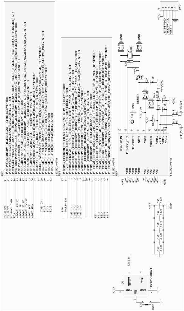
[0034] Example 2, such as Figure 1-2 As shown, the main control module includes a chip U8, the crystal oscillator X1 is connected between the 8 and 9 pins of the chip U8, and the crystal oscillator X2 is connected between the 12 and 13 pins, and the two ends of the crystal oscillator X2 are respectively connected by capacitors C26 and C27. Grounding, the 72 and 76 pins of the chip U8 are respectively connected to the 2 and 3 pins of the interface J2, the first lead of the 14 pins of the chip U8 is connected to the 4 pins of the interface J2, and the second lead is connected to the chip The 1 pin of U9, the pull-up resistor R42 is set at the 14 pin of the chip U8, the capacitor C29 is set between the 14 pin of the chip U8 and the ground, and the 3 pin of the chip U9 passes the button sr1 grounded, the model of the chip U8 is STM32L496VG, and the model of the chip U9 is TPS3823-33DBVT.

[0035] In this embodiment, STM32L496VG is a low-power MCU, interface J2 is a debugging int...

Embodiment 3

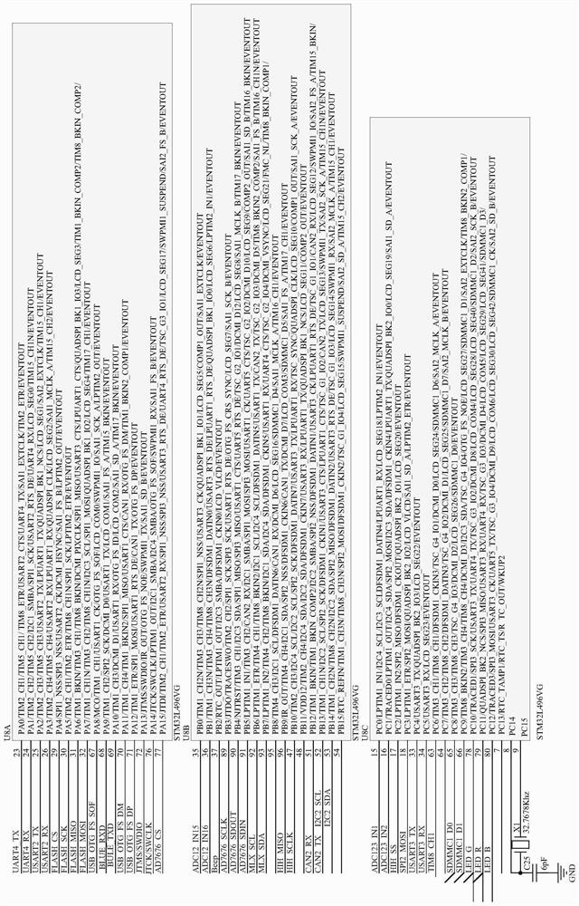
[0036] Example 3, such as Figure 11 As shown, the interface module includes connectors P3 and P5, the connectors P3 and P5 are pin headers, and the 2, 4, 6, 8, 10, 12, 14, 16, 18, 20, 22, 24, 26, 28, 30, 32 pins are respectively connected with 1, 3, 5, 7, 9, 11, 13, 15, 17, 19, 21, 23, 25 of the connector P5 , 27, 29, and 31 pins are connected, and 1, 3, 5, 7, 9, 11, 13, 15, 17, 19, and 21 pins of the connector P3 are respectively connected to 59, 2, and 21 of the chip U8. 3, 4, 542, 43, 44, 45, 46 and 63 pins.

[0037] In this embodiment, the connectors P3 and P5 are pin headers, and the corresponding internal pins (1 and 2 pins, 3 and 4 pins, 5 and 6 pins... …29 and 30 pins, 31 and 32 pins) are connected, the connector J3 is connected to the control acquisition system, and the connector J5 is connected to the infrared luminescence acquisition system, through the plugging between the connectors P3 and P5, the control acquisition system and the The signal transmission betw...

Embodiment 4

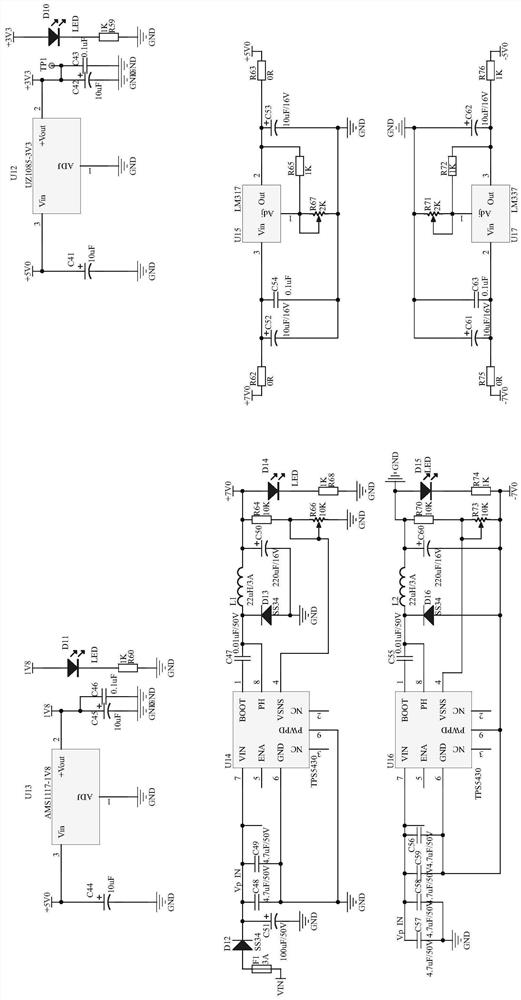
[0038] Example 4, such as image 3 As shown, the power module includes chips U14, U15, U16, U17, U13 and U12, the 7 pins of the chip U14 are connected to the cathode of the diode D12, and the anode of the diode D12 is connected to the input power supply VIN through the fuse F1, so Pin 1 of the chip U14 is connected to the first end of the inductor L1 through the capacitor C47, the first lead wire of the second end of the inductor L1 is connected to a voltage of 7V, the second lead wire is connected to the first end of the resistor R64, and the first end of the resistor R64 The first lead at the two ends is connected to the ground through the resistor R66, the second lead is connected to the 4-pin of the chip U14, the light-emitting diode D14 and the resistor R68 are connected in series and set between the 7V voltage and the ground, and the 3-pin of the chip U15 is connected to the ground through the resistor R62 is connected to 7V voltage, pin 2 is connected to 5V voltage thro...


PUM


Abstract

The invention discloses a road surface state instrument control circuit, and the circuit comprises a control acquisition system and an infrared luminescence acquisition system; the infrared luminescence acquisition system can emit infrared light and acquire infrared signals, and the control acquisition system can judge the road surface state according to the infrared signals and send road surface information and environment information to a user. The control acquisition system and the infrared luminescence acquisition system are connected through an interface module, and the control acquisition system comprises a main control module, and a power supply module, a communication module, a Bluetooth module, an environment detection module, a data conversion module, a storage module and an indication module which are connected with the main control module; and the infrared luminescence acquisition system comprises an infrared LED driving module and an infrared signal receiving module. The road surface state can be judged by integrating the temperature and humidity of the environment where the instrument is located, the road surface temperature and the dew point according to different LED infrared signals of the road surface in various states, and the road surface state detection device has good market application value.

Description

technical field [0001] The invention relates to the field of detection instruments, in particular to a road surface state instrument control circuit. Background technique [0002] With the development of science and technology, more and more detection instruments have been applied to people's lives. Road and traffic detection equipment has also been widely used beside vehicles and roads. Most vehicles now use cameras to collect road traffic information. , but the camera can only take images, and cannot judge and remind the roads of rain, snow, icing, etc. Various states still need people to judge, and the camera function will be greatly reduced when it is dark. Contents of the invention [0003] The present invention aims at the deficiencies of the existing road surface detection equipment, and provides a road surface state instrument control which can judge the state of the road surface according to the difference of LED infrared signals in various states of the road surf...

Claims


Application Information

Patent Timeline
Patent Type & Authority Applications(China)
IPC IPC(8): G05B19/042
CPCG05B19/0423G05B2219/25257
Inventor 邓存芳
Owner SHENZHEN LANSITENG TECH
Why Eureka
Try Eureka