
Finished anode cleaning device

A cleaning device and anode technology, applied in the direction of smoke removal, cleaning methods and appliances, cleaning methods using gas flow, etc., can solve the problems of increased labor intensity, molten iron spilling, waste of manpower and material resources, etc., to improve the cleaning degree and reduce Labor intensity, all-round effect of purging

Active Publication Date: 2021-12-10
SHANDONG HONGQIAO NEW MATERIAL CO LTD
View PDF7 Cites 0 Cited by
  • Summary
  • Abstract
  • Description
  • Claims
  • Application Information

AI Technical Summary

Problems solved by technology

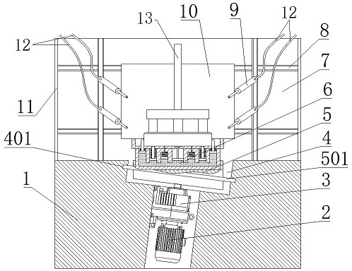
[0003] In the process of pouring molten iron, it is inevitable that there will be molten iron spilled on the upper part of the carbon block. If it is not cleaned and brought into the electrolytic cell, the grade of molten aluminum will be affected. The traditional method is to manually use a slag board to clean it from a long distance, and then manually use a small broom Clean the iron slag with a broom, and finally recycle the manually swept iron slag to the front of the furnace for smelting;
[0004] Due to the need for thorough cleaning, manual cleaning of iron slag on finished anodes is done at close range. In order to clean the iron slag clean enough, it takes a long time to clean it, but there are still fine iron slag that cannot be cleaned. , because the temperature of the casting ring is high, the broom is also wasted seriously, so this cleaning method wastes manpower and material resources, and in the process of cleaning the anode, the personnel are close to the high-temperature casting ring that has just been poured, which increases the work of the workers. Intensity, especially in summer, the work intensity of personnel is more uncontrollable

Method used


Image

  • Finished anode cleaning device
  • Finished anode cleaning device
  • Finished anode cleaning device

Examples


Embodiment Construction

[0023] The following will clearly and completely describe the technical solutions in the embodiments of the present invention with reference to the accompanying drawings in the embodiments of the present invention. Obviously, the described embodiments are only some, not all, embodiments of the present invention. Based on the embodiments of the present invention, all other embodiments obtained by persons of ordinary skill in the art without making creative efforts belong to the protection scope of the present invention.

[0024] In the present invention, unless otherwise clearly specified and limited, terms such as "installation", "connection", "connection" and "fixation" should be understood in a broad sense, for example, it can be a fixed connection or a detachable connection , or integrated; it can be mechanically connected or electrically connected; it can be directly connected or indirectly connected through an intermediary, and it can be the internal communication of two c...


PUM


Abstract

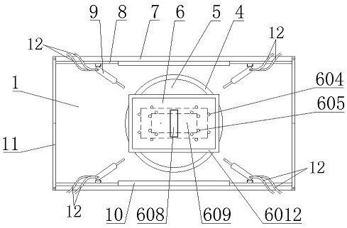
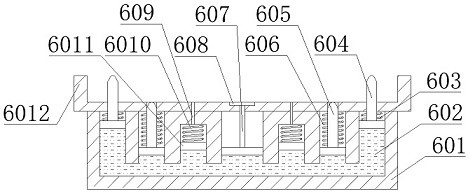
The invention relates to a finished anode cleaning device, and belongs to the technical field of electrolytic aluminum production and manufacturing. The finished anode cleaning device comprises a base; a side wall is mounted on each of two sides of the upper end of the base; a plurality of air blowers are mounted on the inner sides of each side wall; a revolving door is mounted at each of two ends of each side walls. According to the finished anode cleaning device, iron slag that has been dropped after being cleaned by a slag beating plate is blown by high-pressure and high-speed air flow blown out by the air blowers, so that the effect can be better than that of using a small broom, because tiny iron slag cannot be cleaned by using the small broom, but all the iron slag can be cleaned by using air flow blowing; moreover, since an additionally arranged rotating block can drive a finished anode to swing and rotate, the finished anode is blown more comprehensively and cleaned more thoroughly, and meanwhile, a clamping mechanism is additionally arranged, and effectively clamps finished anodes of various sizes, which prevents the finished anode from sliding during swinging and rotating. The finished anode cleaning device effectively improves the cleaning degree of the iron slag of the finished anode.

Description

technical field [0001] The invention relates to the technical field of electrolytic aluminum production and manufacturing, in particular to a finished anode cleaning device. Background technique [0002] The electrolytic aluminum finished anode assembly workshop uses ladles to pour molten iron, connects steel claws with carbon blocks, and assembles finished anodes with good electrical conductivity and sufficient mechanical strength; [0003] In the process of pouring molten iron, it is inevitable that there will be molten iron spilled on the upper part of the carbon block. If it is not cleaned and brought into the electrolytic cell, the grade of molten aluminum will be affected. The traditional method is to manually use a slag board to clean it from a long distance, and then manually use a small broom Clean the iron slag with a broom, and finally recycle the manually swept iron slag to the front of the furnace for smelting; [0004] Due to the need for thorough cleaning, ma...

Claims


Application Information

Patent Timeline
IPC IPC(8): B08B5/02B08B13/00B08B15/04
CPCB08B5/023B08B13/00B08B15/04
Inventor 崔石磊高立节程鸿雁刘书华黄合龙高伟
Owner SHANDONG HONGQIAO NEW MATERIAL CO LTD
Learn More