
Pressure-controllable tile type expansion shaft

A tile type, expansion shaft technology, applied in the direction of couplings, rigid shaft couplings, mechanical equipment, etc., can solve the problems of hard failure of the expansion block mechanism, single fixing force, damage to the inner wall of the core tube, etc. It is not easy to achieve Damage and loosening, avoid excessive force, avoid the effect of hard damage

Pending Publication Date: 2021-12-10
董艳来
View PDF0 Cites 0 Cited by
  • Summary
  • Abstract
  • Description
  • Claims
  • Application Information

AI Technical Summary

Problems solved by technology

[0003] There are hydraulic, pneumatic and mechanical expansion shafts. Pneumatic and hydraulic structures are relatively simple, but they have higher requirements for sealing and additional equipment is required to provide pressure. Therefore, the industry currently has a general trend of adopting mechanical expansion shafts. , but the fixing force provided in the mechanical expansion shaft is single and cannot be adjusted. If the force applied by the expansion block is not enough, the effect of fixing the core tube on the expansion shaft cannot be realized. If the force applied by the expansion block is too large, it may cause The inner wall of the core tube is damaged due to too much load
On the other hand, if due to accidental factors, such as machine failure, vibration, etc., the load imposed by the core tube on the expansion shaft exceeds the load of the expansion block, it is easy to cause hard damage to the expansion block and related mechanical components, resulting in relatively large big loss
[0004] Secondly, the mechanical components in the expansion shaft fix the expansion tiles. After a long time of use, the mechanical components are easy to loosen, so that the expansion shaft cannot fix the core tube.

Method used


Image

  • Pressure-controllable tile type expansion shaft
  • Pressure-controllable tile type expansion shaft
  • Pressure-controllable tile type expansion shaft

Examples


Embodiment Construction

[0021] The following will clearly and completely describe the technical solutions in the embodiments of the present invention with reference to the accompanying drawings in the embodiments of the present invention. Obviously, the described embodiments are only some, not all, embodiments of the present invention. Based on the embodiments of the present invention, all other embodiments obtained by persons of ordinary skill in the art without making creative efforts belong to the protection scope of the present invention.

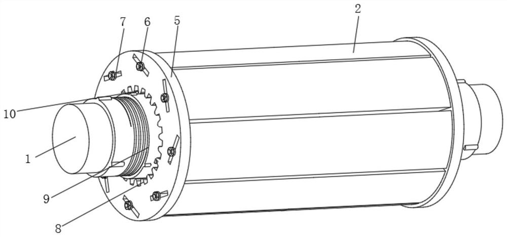
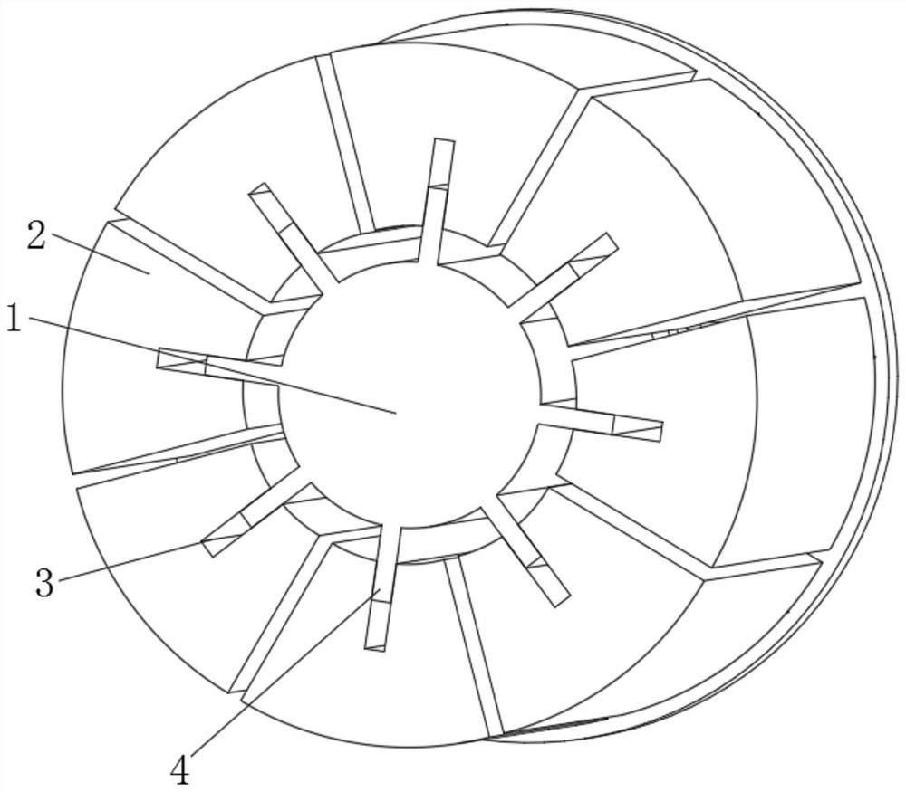
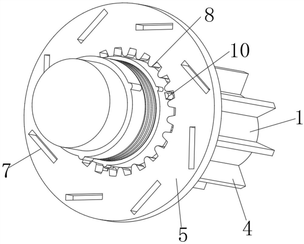
[0022] see figure 2 , a pressure-controllable tile-type expansion shaft, including an inner shaft 1 connected to an external power source, the outer wall of the inner shaft 1 is provided with a plurality of fan-shaped tiles 2 that can be spliced ​​into a cylinder, the inner shaft 1 and The fan-shaped tiles 2 are coaxially arranged, the middle part of the fan-shaped tiles 2 is provided with a chute 3 facing the shaft, the outer wall of the inner shaft 1 is pro...


PUM


Abstract

The invention relates to the technical field of expansion shafts, and discloses a pressure-controllable tile type expansion shaft which comprises an inner shaft in transmission connection with an external power source, a plurality of fan-shaped tiles capable of being spliced into a cylinder are arranged on the outer side wall of the inner shaft, and a sliding groove facing the shaft is formed in the middle of each fan-shaped tile. The pressure-controllable tile type expansion shaft can provide adjustable opening acting force, can be suitable for more application occasions, can also ensure fixation and avoid the situation that the acting force is too large and a core pipe is damaged by expansion, can also automatically realize force unloading, avoid hard damage and ensure the intact condition of equipment when an accident occurs, and during the working process, part of the opening acting force can be converted into centrifugal force of the fan-shaped tiles, namely, the stress between fixed driving teeth and fixed driven teeth is small, damage and looseness are not prone to occurring, in terms of the structure, the driving teeth can be always kept to be tightly attached to the driven teeth, looseness cannot occur, and normal work of the expansion shaft is always kept.

Description

technical field [0001] The invention relates to the technical field of expansion shafts, in particular to a tile-type expansion shaft with controllable pressure. Background technique [0002] The surface of the expansion shaft can be raised, which is used to lock the external tubular parts, and is widely used in packaging and printing, paper-making films, and lithium battery equipment. [0003] There are hydraulic, pneumatic and mechanical expansion shafts. Pneumatic and hydraulic structures are relatively simple, but they have higher requirements for sealing and additional equipment is required to provide pressure. Therefore, the industry currently has a general trend of adopting mechanical expansion shafts. , but the fixing force provided in the mechanical expansion shaft is single and cannot be adjusted. If the force applied by the expansion block is not enough, the effect of fixing the core tube on the expansion shaft cannot be realized. If the force applied by the expan...

Claims


Application Information

Patent Timeline
Patent Type & Authority Applications(China)
IPC IPC(8): F16D1/08
CPCF16D1/08F16D1/0829
Inventor 董艳来
Owner 董艳来
Learn More