Anti-gushing and anti-scalding device for clearing blockage of cyclone preheater of cement kiln

A cyclone preheater and anti-splash technology, which is applied in the direction of preheating fee, descaling device, lighting and heating equipment, etc., can solve the problems of unblocking personnel's operation injury, material splashing, etc.

Pending Publication Date: 2021-12-10
GUANGXI YUFENG CEMENT
View PDF12 Cites 1 Cited by
  • Summary
  • Abstract
  • Description
  • Claims
  • Application Information

AI Technical Summary

Problems solved by technology

During the cleaning process, it is inevitable that there will be material splashes, and some will fly out from the inspection hole, and high-temperature materials are likely to cause damage to the cleaning personnel.

Method used


Image

  • Anti-gushing and anti-scalding device for clearing blockage of cyclone preheater of cement kiln
  • Anti-gushing and anti-scalding device for clearing blockage of cyclone preheater of cement kiln
  • Anti-gushing and anti-scalding device for clearing blockage of cyclone preheater of cement kiln

Examples


Embodiment 1

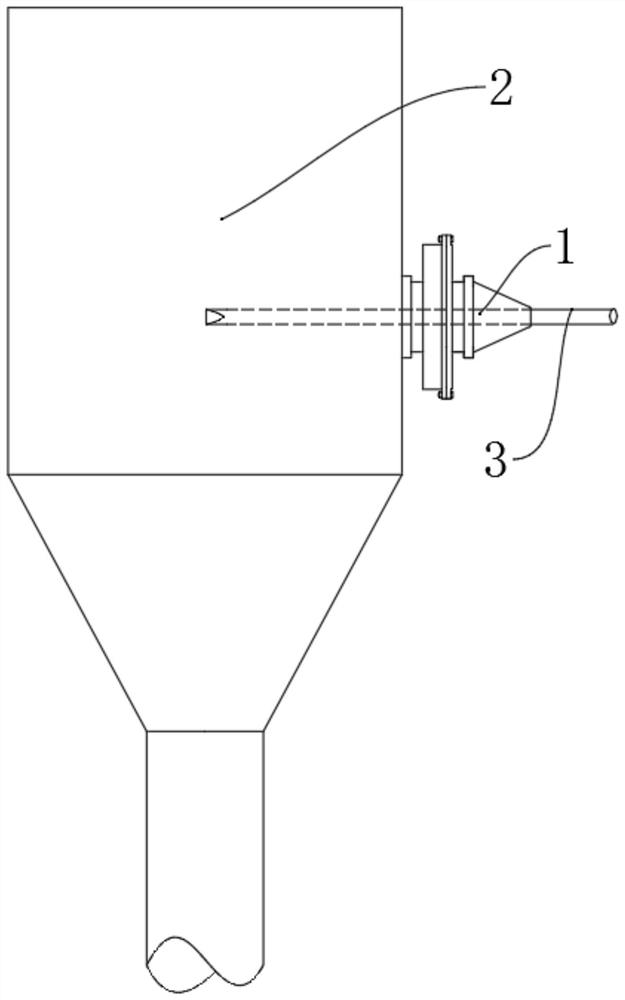
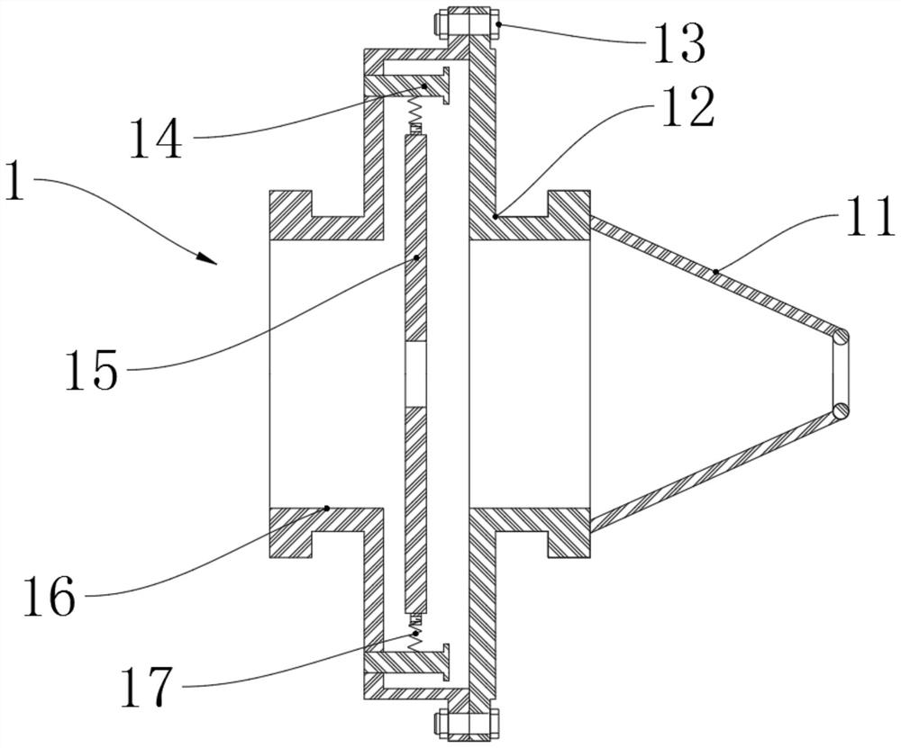
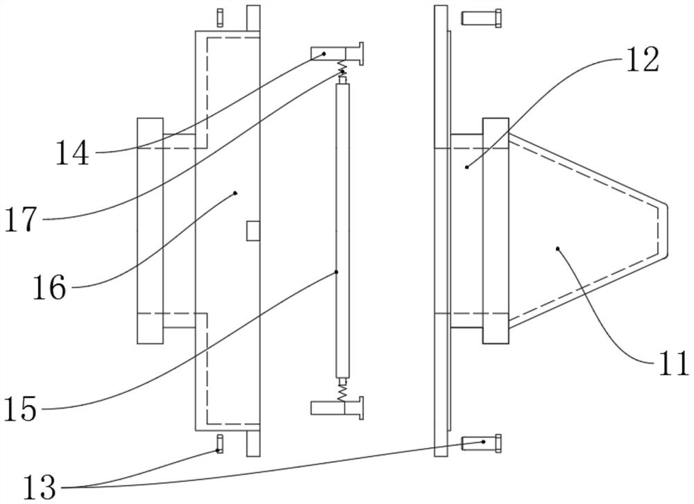
[0032] Such as Figure 1-11 As shown, a kind of anti-spray scald device for clearing the blockage of a cyclone preheater in a cement kiln, said anti-spray scald device includes a support seat 16, a baffle plate 15, a support column 14, a spring 17, a protective piece 12 and a protective cover 11; One end of the support seat 16 is connected to the cyclone preheater 2, and the other end is movably connected to one end of the protective member 12, and the other end of the protective member 12 is connected to the protective cover 11; the support seat 16 is provided with a connection hole 162 and the counterbore 163, at least two symmetrical support columns 14 are distributed on the bottom circumference of the counterbore 163; the baffle plate 15 is placed in the counterbore 163, and is connected with the support column 14 by a spring 17, and is suspended in the air. Inside the counterbore 163 , the baffle plate 15 defines a first through hole 151 .

[0033] When the baffle plate ...

Embodiment 2

[0040] Compared with Embodiment 1, the difference lies in that: a connection structure form of the support seat and the protective member is provided.

[0041] The support base 16 is connected to the protective member 12 through bolts 13 . The bolts can facilitate splicing and separation between the support seat and the protective piece.

Embodiment 3

[0043] Compared with Embodiment 2, the difference is that: in order to facilitate the connection between the support seat and the protective member, a support 161 is added; in order to facilitate the installation of the support column in the counterbore, a support hole 164 is added.

[0044] At least two supports 161 are distributed on the circumferential side of the supporting seat 16 . The support 161 is used for the movable connection between the support seat and the protective element. The commonly used number of bearings 161 is 2, 3, 4, 6 or 8, etc.

[0045]One end of the screw rod in the bolt 13 passes through the guard 12 and the support 161 and is connected with the nut.

[0046] A plurality of support holes 164 are distributed around the bottom surface of the counterbore 163 , and the support holes 164 are used for installing the support column 14 .

[0047] The support column 14 is inserted into the support hole 164 and is firmly connected with the support hole 164...


PUM


Abstract

The invention discloses an anti-gushing and anti-scalding device for clearing blockage of a cyclone preheater of a cement kiln. The anti-gushing and anti-scalding device for clearing blockage of the cyclone preheater of the cement kiln comprises a supporting base, a baffle, a supporting column, a spring, a protection piece and a protection sleeve, one end of the supporting base is connected with the cyclone preheater, the other end of the supporting base is movably connected with one end of the protection piece, and the other end of the protection piece is connected with the protection sleeve; the supporting base is provided with a connecting hole and a counter bore, and at least two symmetrical supporting columns are distributed on the circumference of the bottom of the counter bore; the baffle is arranged in the counter bore, connected with the supporting column through a spring and suspended in the counter bore, and a first through hole is formed in the baffle. According to the anti-gushing and anti-scalding device for clearing blockage of the cyclone preheater of the cement kiln, the anti-gushing and anti-scalding device has the characteristics that an anti-blocking device can be used for protecting the cyclone preheater of the cement kiln during blocking removal, and can effectively avoid injury to operators during blocking removal, and the like.

Description

technical field [0001] The invention relates to an anti-spray scalding device for unclogging a cyclone preheater of a cement kiln. Background technique [0002] In the cement production process, the raw meal powder with a fineness of 15±2% is preheated and decomposed in the suspension state in the preheaters at all levels of the cyclone preheater system at a temperature of 300-900 ° C. During the decomposition process, due to The mismatch of operating parameters such as temperature, feeding amount, coal consumption, and system air volume will lead to blockage in the cyclone of a certain stage of preheater or the location of the feeding pipe, or the material is viscous and has poor fluidity, or the cyclone is large. The block crust falls off, or the pouring material in the cyclone falls off, causing a blockage failure. If the blockage cannot be cleared in time, the raw meal powder will become sticky and sintered under high temperature conditions, forming a large hard agglome...

Claims


Application Information

Patent Timeline
Patent Type & Authority Applications(China)
IPC IPC(8): F27D25/00F27D13/00
CPCF27D25/00F27D13/00
Inventor 莫锐覃泽奋黄运敏刘骥韦俊美韦裕光饶轩陆金海巫裕旋隆盛康
Owner GUANGXI YUFENG CEMENT
Why Eureka
Try Eureka