Device and method for measuring real-time heat flux density of wall surface of combustion chamber

A heat flux density, measuring device technology, applied in gas turbine engine testing, material thermal development, jet engine testing and other directions, can solve the problems of low measurement accuracy, inability to realize the combustion chamber wall, long response time, etc., to achieve high measurement accuracy, The effect of shortened thermal response time and convenient processing

Active Publication Date: 2021-12-10
XIAN AEROSPACE PROPULSION INST
View PDF5 Cites 0 Cited by
  • Summary
  • Abstract
  • Description
  • Claims
  • Application Information

AI Technical Summary

Problems solved by technology

[0004] The purpose of the present invention is to solve the technical problems that the heat flux density measurement method on the wall surface of the combustion chamber has a long response time and low measurement accuracy and cannot realize real-time measurement of the heat flux density on the wall surface of the combustion chamber in the prior art, and provides a real-time measurement method for the wall surface of the combustion chamber. Heat flux measuring device and measuring method

Method used


Image

  • Device and method for measuring real-time heat flux density of wall surface of combustion chamber
  • Device and method for measuring real-time heat flux density of wall surface of combustion chamber
  • Device and method for measuring real-time heat flux density of wall surface of combustion chamber

Examples


Embodiment Construction

[0044] The present invention will be further described below with reference to the accompanying drawings and specific embodiments.

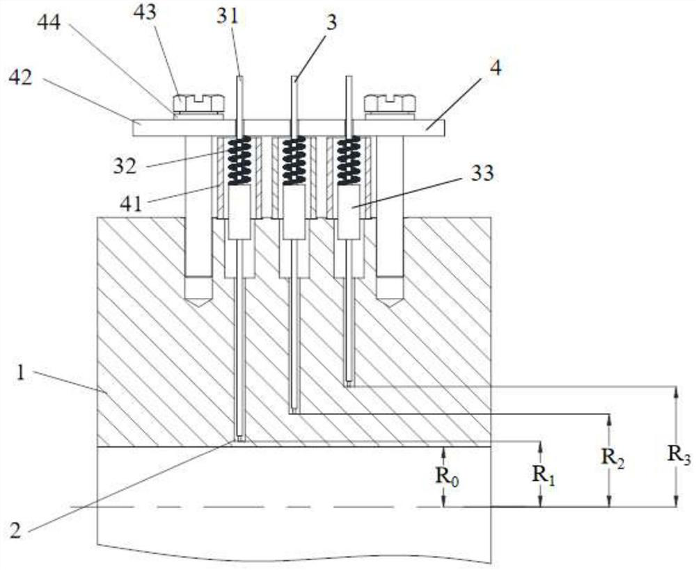
[0045] like Figure 1 to Figure 3 As shown, a real-time heat flux density measurement device on a combustion chamber wall surface includes a heat conductive combustion chamber wall 1, a measuring component 3 and a fixed limit component 4, and the combustion chamber wall 1 is a tubular structure;

[0046]A group of measuring holes is drilled in a radially arranged and axially arranged manner along the direction where the outer wall of the combustion chamber faces the inner wall of the combustion chamber, and one group of measuring holes is three blind holes 2 . In this embodiment, the blind holes 2 are stepped blind holes, the three stepped blind holes are on the same straight line, and the depth difference of adjacent stepped blind holes is the same. The position of the step blind hole is flexible and adjustable, which is determined according to...


PUM

PropertyMeasurementUnit
diameteraaaaaaaaaa
diameteraaaaaaaaaa
diameteraaaaaaaaaa

Abstract

The invention relates to a heat flux density measurement technology, in particular to a device and method for measuring the real-time heat flux density of a wall surface of a combustion chamber, and mainly solves the technical problems of long thermal response time, low measurement precision and incapability of real-time measurement in measurement of the wall surface of the combustion chamber in the prior art. The device comprises a combustion chamber wall, a measuring hole, a measuring assembly and a fixing and limiting assembly. Measuring holes are formed in the combustion chamber wall; thermocouples are arranged in the measuring holes; the thermocouples contacts with the bottom of the measuring holes; the thermocouples are sleeved with fixing sleeves, and limiting holes are formed in the thermocouple fixing plate. The thermocouple fixing plate is fixedly connected with the wall of the combustion chamber, the fixing sleeve is pressed and fixed between the outer wall face of the combustion chamber and the thermocouple fixing plate, and springs are compressed between check blocks and the thermocouple fixing plate. The fixing sleeves, the springs, the check blocks and the thermocouple fixing plate are combined to form a spring compensation type thermocouple fixing method. Meanwhile, the invention also provides a method for measuring the real-time heat flux density of the wall surface of the combustion chamber.

Description

technical field [0001] The invention relates to a heat flux density measurement technology, in particular to a real-time heat flux density measurement device and a measurement method for a combustion chamber wall surface. Background technique [0002] The gas temperature in the combustion chamber of the aerospace engine is as high as 3000K or more, and the working thermal environment in the combustion chamber is extremely harsh, which has high requirements for the thermal protection of the combustion chamber wall. The heat flux density of the combustion chamber wall is an extremely important physical quantity for evaluating the material of the combustion chamber wall. Accurately obtaining the real-time heat flux density of the combustion chamber wall can quantitatively evaluate the local heat transfer characteristics of the combustion chamber wall, and then guide the optimization of the thermal protection structure of the combustion chamber wall. Reflect the combustion state...

Claims


Application Information

Patent Timeline
Patent Type & Authority Applications(China)
IPC IPC(8): G01M15/14G01N25/22
CPCG01M15/14G01N25/22
Inventor 刘昭宇薛帅杰李悦王焕燃熊剑房喜荣肖虹
Owner XIAN AEROSPACE PROPULSION INST
Why Eureka
Try Eureka