Measuring device and method for visualizing propagation state and characteristics of high-speed deflagration waves

A measuring device and deflagration wave technology, applied in measuring devices, using combustion for chemical analysis, and optical means for material analysis, etc., can solve problems such as bulky, expensive lasers, and poor shooting effects

Pending Publication Date: 2021-12-10
SHANGHAI JIAO TONG UNIV
View PDF6 Cites 0 Cited by
  • Summary
  • Abstract
  • Description
  • Claims
  • Application Information

AI Technical Summary

Problems solved by technology

[0004] The disadvantage of the existing technology is: the data measurement method lacks an intuitive understanding of the evolution of the deflagration wave during the propagation process, and can only reproduce the state changes during the deflagration wave propagation through the captured real-time pressure / light signals; The same is true for the trace method, which analyzes the morphological evolution of the combustion wave during the propagation process by analyzing the specific structural "cell" shape left on the smoked foil during the propagation of the combustion wave
High-frequency lasers are generally used at home and abroad, but the lasers are expensive and cumbersome; the use of incandescent lamps as light sources is only suitable for the visualization of low-speed flame wave propagation, and the flame propagation speed is mostly around 100m / s, while for high-speed deflagration waves , especially when the flame propagation speed is above 500m / s, the incandescent lamp as the light source will cause the camera to overexposure and the shooting effect will not be good

Method used


Image

  • Measuring device and method for visualizing propagation state and characteristics of high-speed deflagration waves
  • Measuring device and method for visualizing propagation state and characteristics of high-speed deflagration waves
  • Measuring device and method for visualizing propagation state and characteristics of high-speed deflagration waves

Examples


Embodiment Construction

[0027] The present invention will be further described below in conjunction with specific embodiments. It should be understood that the following examples are only used to illustrate the present invention but not to limit the scope of the present invention.

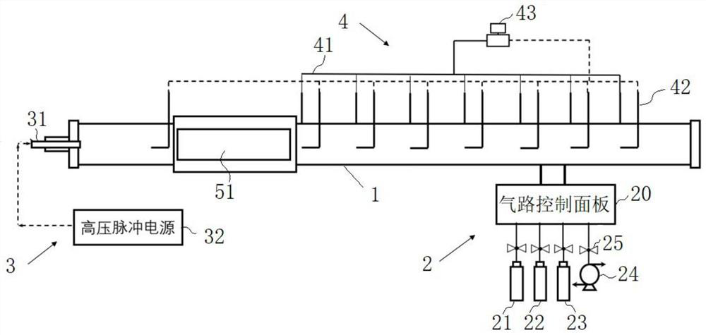
[0028] like figure 1 Shown is a measurement device for visualizing the state and characteristics of high-velocity deflagration wave propagation according to an embodiment of the present invention, and the measurement device is installed on a shock tube experiment platform. The shock tube experiment platform includes a shock tube 1 , and a gas circuit control system 2 , an ignition system 3 and a data acquisition system 4 installed on the shock tube 1 .

[0029] The ignition system 3 includes an ignition head 31 installed at one end of the shock tube and a pulse igniter 32 connected with the ignition head 31 . The ignition system 3 is connected to the shock tube 1 through an ignition head 31 , and the ignition head 31 is...


PUM


Abstract

The invention provides a measuring device for visualizing the propagation state and characteristics of high-speed deflagration waves, which comprises a streak window arranged on the side wall of a shock tube of a shock tube experimental platform, a pair of primary mirrors arranged on the two sides of the streak window, a high-frequency LED light source arranged on the upstream of a light path of the primary mirrors, a high-speed camera arranged on the downstream of the light path of the primary mirrors, and a digital delay generator connected with the high-frequency LED light source and the high-speed camera. The invention further provides a corresponding measuring method. The measuring device comprises a signal triggering system connected with the LED light source and the high-speed camera, so that the flash frequency of the light source is synchronous with the shooting frequency of the high-speed camera, and the whole process of detonation wave propagation can be captured. The device is simple in composition and good in operability, and the capturing difficulty of high-speed deflagration waves in the schlieren experiment is reduced.

Description

technical field [0001] The invention belongs to the technical field of deflagration experiments, and in particular relates to a measuring device and method for visualizing the propagation state and characteristics of high-speed deflagration waves. Background technique [0002] A deflagration wave is a burning wave that travels at subsonic speed. It is widely used in the fields of daily industrial production safety and power propulsion. Due to its strong instability, deflagration can easily transition to detonation through the DDT (deflagration-to-detonation) process, thus becoming a research hotspot in the field of combustion and detonation physics. The composition of the deflagration wave can be briefly described as a coupling structure of leading shock wave-induction zone-flame surface. Generally, with the self-acceleration of the flame, the intensity of the leading shock wave will become stronger due to the acceleration of the combustion rate and the increase of heat re...

Claims


Application Information

Patent Timeline
Patent Type & Authority Applications(China)
IPC IPC(8): G01N31/12G01N21/84
CPCG01N31/12G01N21/84
Inventor 张博程俊刘洪
Owner SHANGHAI JIAO TONG UNIV
Why Eureka
Try Eureka