Unmanned vehicle path planning method and device, electronic equipment, unmanned vehicle and medium
A technology for path planning and unmanned vehicles, applied in vehicle position/route/height control, non-electric variable control, two-dimensional position/channel control, etc., can solve the problem of low success rate of path planning
- Summary
- Abstract
- Description
- Claims
- Application Information
AI Technical Summary
Problems solved by technology
Method used
Image
Examples
Embodiment 1
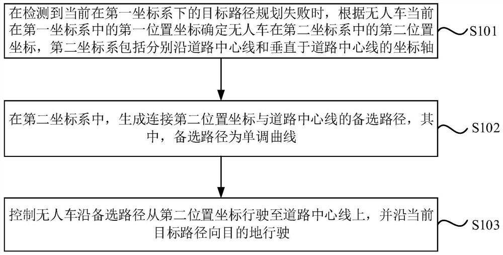
[0032] figure 1 It is a flow chart of the path planning method for unmanned vehicles provided in Embodiment 1 of the present invention. The technical solution of this embodiment is applicable to the situation where the unmanned vehicle quickly returns to the centerline of the road through an alternative route when the target route planning fails. The method can be executed by the unmanned vehicle path planning device provided in the embodiment of the present invention, the device can be implemented in the form of software and / or hardware, and configured and applied in the controller of the unmanned vehicle. The method specifically includes the following steps:
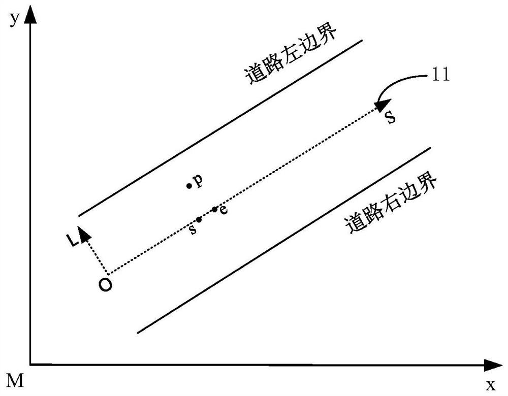
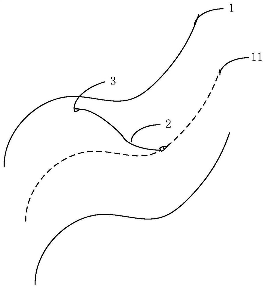
[0033] S101. When it is detected that the current target path planning in the first coordinate system fails, determine the second position coordinates of the unmanned vehicle in the second coordinate system according to the current first position coordinates of the unmanned vehicle in the first coordinate system , th...
Embodiment 2
[0067] Figure 4 It is a structural block diagram of the unmanned vehicle path planning device provided by the second embodiment of the present invention. The device is used to execute the path planning method for the unmanned vehicle provided in any of the above embodiments, and the device can be implemented in software or hardware. The device includes
[0068] The coordinate conversion module 41 is used to determine the position of the unmanned vehicle in the second coordinate system according to the current first position coordinates of the unmanned vehicle in the first coordinate system when detecting that the current target path in the first coordinate system fails. The second position coordinates, the second coordinate system includes coordinate axes respectively along the centerline of the road and perpendicular to the centerline of the road;
[0069] The alternative path module 42 is used to generate an alternative path connecting the second position coordinates and ...
Embodiment 3
[0081] Figure 5 A schematic structural diagram of the electronic device provided in Embodiment 3 of the present invention, such as Figure 5 As shown, the device includes a processor 501, a memory 502, an input device 503, and an output device 504; the number of processors 501 in the device may be one or more, Figure 5 Take a processor 501 as an example; the processor 501, memory 502, input device 503, and output device 504 in the device can be connected by bus or other methods, Figure 5 Take connection via bus as an example.
[0082] Memory 502, as a computer-readable storage medium, can be used to store software programs, computer-executable programs and modules, such as program instructions / modules corresponding to the unmanned vehicle path planning method in the embodiment of the present invention (for example, the coordinate conversion module 41 , alternative path module 42 and travel module 43). The processor 501 executes various functional applications and data pr...
PUM
 Abstract
Description
Claims
Application Information
 - R&D
- Intellectual Property
- Life Sciences
- Materials
- Tech Scout
- Unparalleled Data Quality
- Higher Quality Content
- 60% Fewer Hallucinations
Browse by: Latest US Patents, China's latest patents, Technical Efficacy Thesaurus, Application Domain, Technology Topic, Popular Technical Reports.
© 2025 PatSnap. All rights reserved.Legal|Privacy policy|Modern Slavery Act Transparency Statement|Sitemap|About US| Contact US: help@patsnap.com


