
Submersible pump rotor with high stability

A submersible pump and stability technology, which is applied in the field of submersible pump rotors, can solve problems such as unsatisfactory use requirements, simplification of functions, and impact on stability, and achieve the effects of saving resources, reducing consumption, and improving stability

Pending Publication Date: 2021-12-10
XUZHOU MINGRUN MAGNETIC MATERIAL CO LTD
View PDF2 Cites 0 Cited by
  • Summary
  • Abstract
  • Description
  • Claims
  • Application Information

AI Technical Summary

Problems solved by technology

[0011] The purpose of the present invention is to provide a submersible pump rotor with high stability. By setting a stabilizing mechanism, a volume control mechanism and a heat dissipation mechanism, the existing submersible pump rotor generally relies on fastening to improve its own stability, while lubricating The lack of performance also affects its own stability, or the structure used for lubrication has no control structure, and a large amount of lubricating oil is directly discharged, resulting in waste of resources and increasing costs. At the same time, the structure itself only has lubrication Features, single function, unable to meet the needs of use

Method used


Image

  • Submersible pump rotor with high stability
  • Submersible pump rotor with high stability
  • Submersible pump rotor with high stability

Examples


Embodiment Construction

[0046] The following will clearly and completely describe the technical solutions in the embodiments of the present invention with reference to the drawings in the embodiments of the present invention.

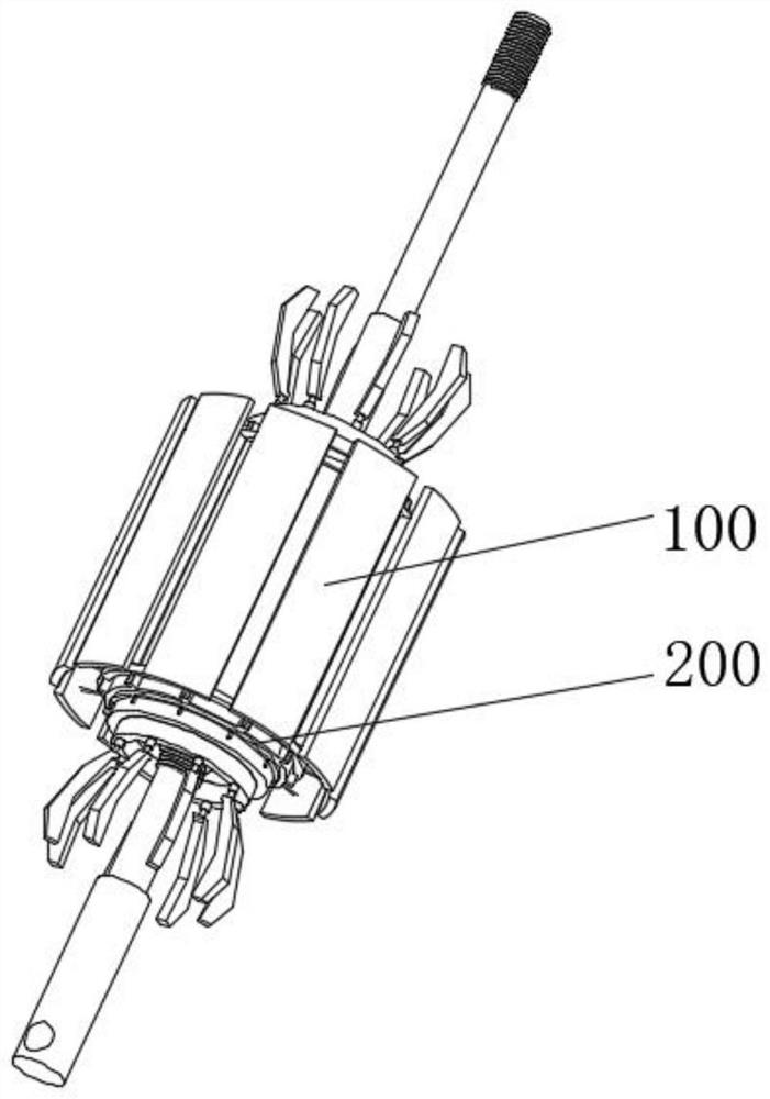
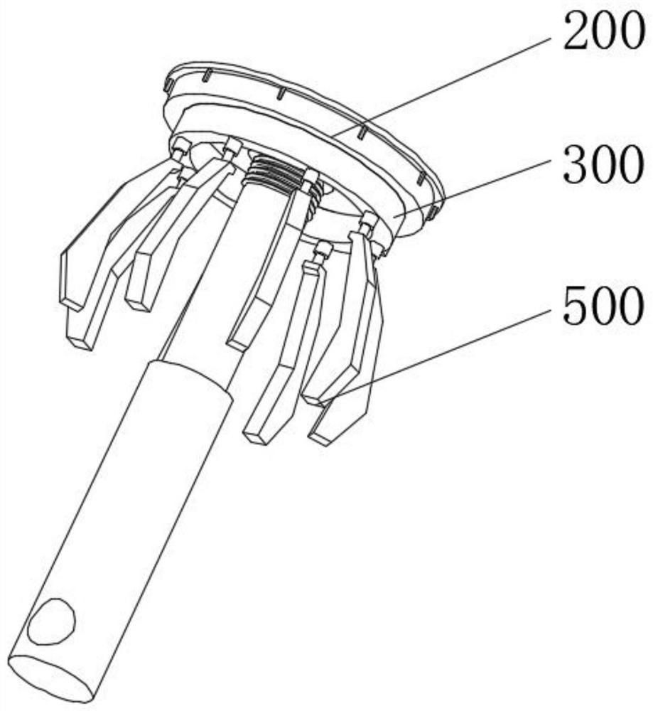
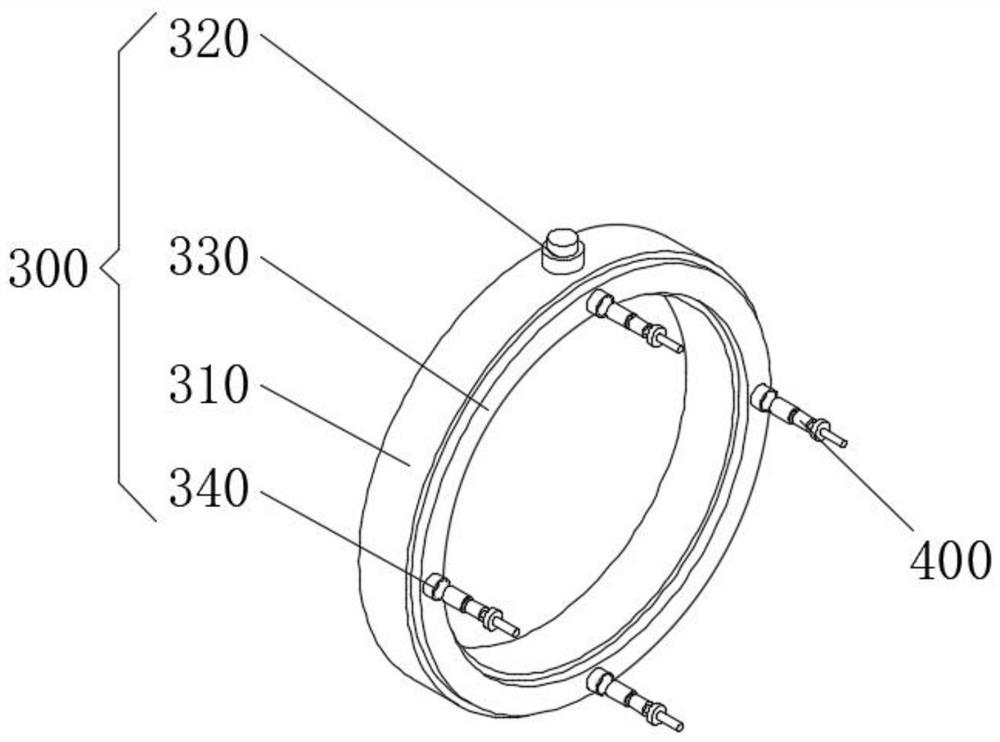
[0047] see Figure 1-9 As shown, the present invention is a submersible pump rotor with high stability, including a rotor mechanism 100, a stabilizing mechanism 300, a volume control mechanism 400 and a heat dissipation mechanism 500. The end of the rotor mechanism 100 is connected with a shaft seat 200, and the shaft seat 200 The middle part is fixedly connected with a stabilizing mechanism 300 , and a set of oil supply tanks 310 included in the stabilizing mechanism 300 is penetrated with a stud 320 in the upper middle, and the outer end of the cover plate 330 in the middle of the inner end of the fuel supply tank 310 is equidistantly penetrated with oil supply pipes 340 ;

[0048] The inner wall of the oil supply tank 310 is equidistantly connected with the volume control m...


PUM


Abstract

The invention discloses a submersible pump rotor with high stability, which relates to the technical field of structures for mechanical equipment. The submersible pump rotor with high stability comprises a rotor mechanism, a stabilizing mechanism, a quantity control mechanism and a heat dissipation mechanism, a shaft seat is connected to the end of the rotor mechanism, the stabilizing mechanism is fixedly connected to the outer middle of the shaft seat, a stud penetrates through the upper middle of a group of oil supply tanks included in the stabilizing mechanism, and oil supply pipes penetrate through the outer end of a cover plate in the middle of the inner end of each oil supply tank at equal intervals; the inner side wall of the oil supply tank penetrates through the oil supply pipe and is connected with quantity control mechanisms at equal intervals, and the middle of the outer end of the oil supply tank is connected with heat dissipation mechanisms at equal intervals. By arranging the stabilizing mechanism, the quantity control mechanism and the heat dissipation mechanism, the problems that the stability of an existing submersible pump rotor is generally improved by means of a fastening mode, the lubricity is insufficient, the stability of the submersible pump rotor is also influenced, or a large amount of lubricating oil of a lubricating structure is directly discharged outwards, so that resources are wasted, and meanwhile the lubricating structure is single in function and cannot meet the use requirement can be solved.

Description

technical field [0001] The invention belongs to the technical field of structures for mechanical equipment, in particular to a submersible pump rotor with high stability. Background technique [0002] Submersible pump is an important equipment for deep well water extraction. When in use, the whole unit dives into the water and extracts groundwater to the surface. It is used for domestic water, mine rescue, industrial cooling, farmland irrigation, seawater lifting, ship loading, and fountain landscape. Hot water submersible pumps are used for bathing in hot springs, and are also suitable for extracting groundwater from deep wells. They can also be used in rivers, reservoirs, canals, etc. The rotor is a submersible pump structure, and its function is to output torque. [0003] After retrieval, China Authorized Patent No. CN206412856U, authorized publication date 2017.08.15, authorized to disclose a motor rotor with high stability, including iron core and magnetic steel, the m...

Claims


Application Information

Patent Timeline
IPC IPC(8): H02K1/32H02K5/16H02K5/132
CPCH02K1/32H02K5/16H02K5/132
Inventor 刘干滨
Owner XUZHOU MINGRUN MAGNETIC MATERIAL CO LTD
Learn More