Heat dissipation structure of servo driver

A technology of a servo drive and a heat dissipation structure, applied in the field of servo drives, can solve the problems of short circuit of the servo drive, affecting the heat dissipation effect of the equipment, and low heat dissipation efficiency, and achieve the effect of improving the heat dissipation efficiency.

Active Publication Date: 2021-12-10
杭州通航电驱科技有限公司
View PDF10 Cites 1 Cited by
  • Summary
  • Abstract
  • Description
  • Claims
  • Application Information

AI Technical Summary

Problems solved by technology

Due to the dust in the air, the dust will adhere to the surface of the driver during the air flow process, which will easily cause a short circuit of the servo driver and affect the heat dissipation of the servo driver.
When the existing servo driver dissipates heat, the driver is installed on the heat sink, and the heat is transferred to the heat sink by means of heat conduction, increasing the heat dissipation area for passive heat dissipation, and the heat dissipation efficiency is low. Dust adheres, which affects the heat dissipation effect of the equipment. It is necessary to disassemble the heat sink and clean the dust. The operation method is complicated. Therefore, how to design a heat dissipation structure that improves the air-cooled heat dissipation efficiency and reduces the complexity of dust cleaning has become a technology in the art. Technological issues that people need to solve

Method used


Image

  • Heat dissipation structure of servo driver
  • Heat dissipation structure of servo driver
  • Heat dissipation structure of servo driver

Examples


Embodiment

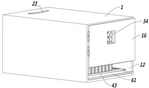
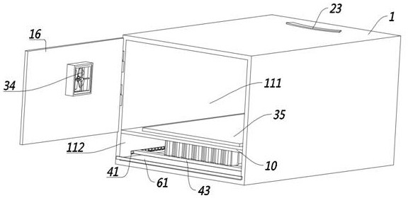
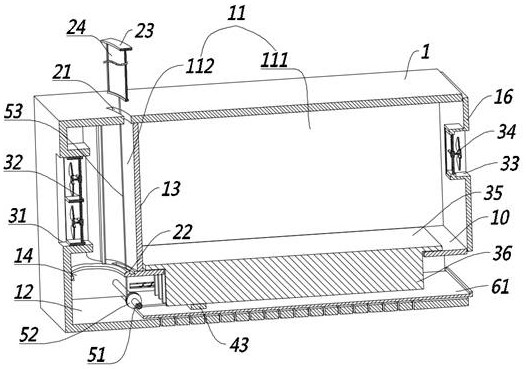
[0032] This embodiment provides a heat dissipation structure of the servo drive, which mainly uses the heat dissipation of the servo drive to increase the heat dissipation efficiency of the heat dissipation plate, prevent dust from interfering with the equipment, and simplify the way of cleaning the heat sink dust.

[0033] Including the casing 1, the inner cavity of the casing 1 is fixed with a partition 10 separating the inner cavity of the casing 1 into a first cavity 11 and a second cavity 12, and the partition 10 is provided with The first cavity 11 is divided into the windshield assembly of the driver installation chamber 111 and the air inlet chamber 112, the windshield assembly includes an arc-shaped windshield 13 fixed on the partition 10, and the two windshields 13 The air inlet chamber 112 is provided with a dust filter mechanism extending out of the upper end surface of the casing 1, and the partition 10 is provided with a connection between the air inlet chamber 11...


PUM


Abstract

The invention relates to the technical field of servo drivers, in particular to a heat dissipation structure of a servo driver, which comprises a machine shell. A partition plate for dividing an inner cavity of the machine shell into a first cavity and a second cavity is fixedly arranged in the inner cavity of the machine shell, and a wind shielding assembly for dividing the first cavity into a driver mounting cavity and an air inlet cavity is arranged on the partition plate. The wind shielding assembly comprises an arc-shaped wind shielding plate fixed to the partition plate, flow guiding plates for guiding the air direction are arranged at the two ends of the wind shielding plate, a dust filtering mechanism extending out of the upper end face of the machine shell is arranged in the air inlet cavity, and a heat dissipation plate is installed on the partition plate. The heat dissipation plate is fixedly provided with heat dissipation fins which penetrate through the partition plate and extend into the second cavity, the second cavity is internally provided with a dust cleaning assembly for cleaning the heat dissipation plate in a sliding mode, and the dust filtering mechanism is provided with a pull rope assembly used for pulling the dust cleaning assembly to move. The air cooling heat dissipation efficiency is improved, and interference of dust on equipment is reduced.

Description

technical field [0001] The present invention relates to the technical field of servo drives, in particular, to a heat dissipation structure of a servo drive. Background technique [0002] The servo drive is a controller used to control the servo motor, mainly used in high-precision positioning systems. [0003] During the working process of the servo driver, a large number of digital signals need to be calculated, resulting in a large amount of heat generated by the servo driver. It is necessary to dissipate the heat of the servo driver in time to ensure the stable operation of the servo driver. [0004] The existing heat dissipation methods include air-cooled heat dissipation and water-cooled heat dissipation. Water-cooled heat dissipation: the equipment is compactly installed, the cost of use is high, and the heat dissipation effect is better. The air-cooled radiator runs through the fan to drive the flow of air and blow it to the servo driver to realize the heat dissipat...

Claims


Application Information

Patent Timeline
Patent Type & Authority Applications(China)
IPC IPC(8): H05K7/20H05K5/02B08B1/00
CPCH05K7/20181H05K7/2019H05K7/20145H05K7/20154H05K7/2039H05K5/0217B08B1/005
Inventor 江冬华
Owner 杭州通航电驱科技有限公司
Why Eureka
Try Eureka