
Spinning device capable of protecting needle head

A needle and protective cover technology is applied to the field of textile devices that can protect the needle, and can solve the problems that the needle cannot be protected, the staff is injured, the needle is damaged, etc., so as to improve the efficiency of textile work, facilitate installation and disassembly, and improve comfort. sexual effect

Inactive Publication Date: 2021-12-14
SUZHOUBIDAER INNOVATION MATERIALS TECH CO LTD
View PDF1 Cites 0 Cited by
  • Summary
  • Abstract
  • Description
  • Claims
  • Application Information

AI Technical Summary

Problems solved by technology

[0003] However, after the above invention is used, the needle cannot be protected, and the needle is exposed in the air. If the staff accidentally touches the needle, the needle may be damaged, and in severe cases, the staff may be injured.

Method used

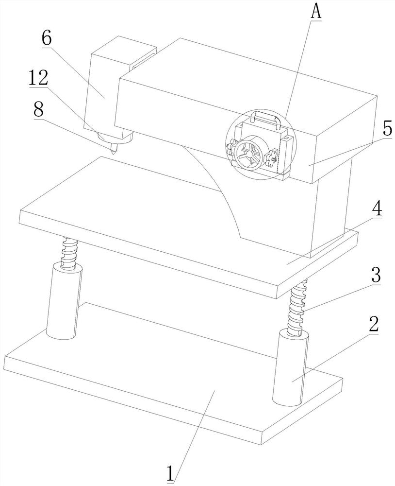

Image

  • Spinning device capable of protecting needle head
  • Spinning device capable of protecting needle head
  • Spinning device capable of protecting needle head

Examples


Embodiment 1

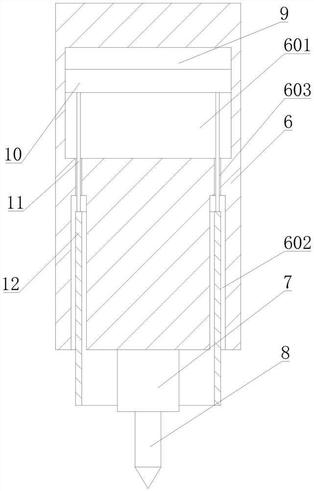
[0026] Such as Figure 1-4 As shown, the present invention proposes a textile device that can protect needles, including a base plate 1, a sleeve rod 2, a machine head 6, a fixed block 7, a needle 8, an electromagnet 9, a magnet 10, a connecting rod 11 and a protective cover 12;

[0027] There are two sleeve rods 2, and the two sleeve rods 2 are respectively arranged on the upper part of the lateral sides of the bottom plate 1; the screw rod 3 is arranged on the sleeve rod 2; the table 4 is arranged on the screw rod 3; the organic body 5 is arranged on the table 4; the machine head 6 Set on the lateral side of the body 5, a cavity 601 is provided in the machine head 6, a placement groove 602 is provided at the bottom of the machine head 6, the placement groove 602 is an annular groove, and two through holes 603 are provided on the inner wall of the bottom of the cavity 601 , two through-holes 603 are distributed along the transverse direction, and the two through-holes 603 are...

Embodiment 2

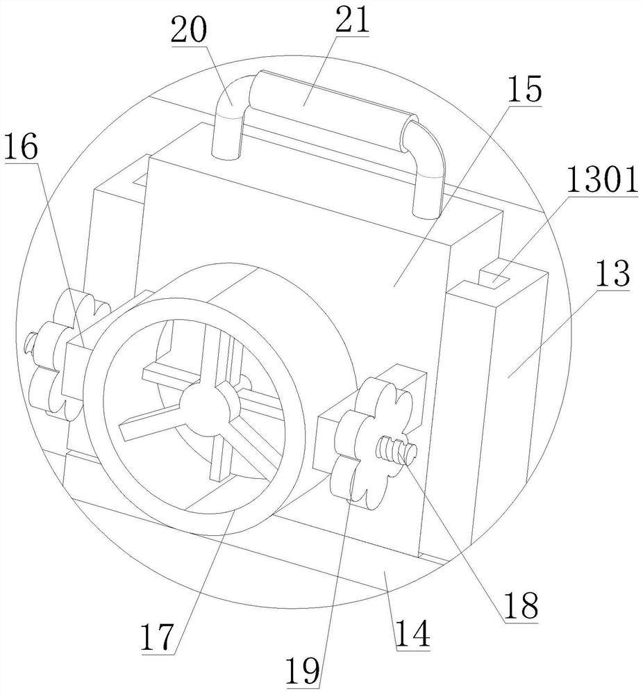
[0033] Compared with Embodiment 1, this embodiment also includes a limiting plate 13, a supporting plate 14 and a cooling device; there are two limiting plates 13, and the two limiting plates 13 are arranged on one longitudinal side of the body 5, The two limiting plates 13 are distributed along the transverse direction; the supporting plate 14 is arranged on the longitudinal side of the body 5, and the supporting plate 14 is located below the two limiting plates 13; the cooling device is slidingly arranged between the two limiting plates 13, and the cooling device is located on the On the supporting plate 14, since the textile device is generally arranged in the factory building, many staff working in the factory building for a long time will cause the temperature of the factory building to rise, which will bring certain discomfort to the staff. Setting the cooling device can cool the staff. Improve the working comfort of the staff.

[0034]The cooling device includes a mount...


PUM


Abstract

The invention discloses a spinning device capable of protecting a needle head, and relates to the technical field of spinning mechanical devices. The spinning device comprises a bottom plate, sleeve rods, a machine head, a fixing block, the needle head, an electromagnet, a magnet, a connecting rod and a protective cover; the two sleeve rods are arranged on the upper portions of the two transverse sides of the bottom plate respectively; screw rods are arranged on the sleeve rods; a tabletop is arranged on the screw rods; a machine body is arranged on the tabletop; the machine head is arranged on one transverse side of the machine body; a cavity is formed in the machine head; a containing groove is formed in the bottom of the machine head and is an annular groove; two through holes are formed in the inner wall of the bottom of the cavity, distributed in the transverse direction and communicated with the containing groove; the fixing block is arranged at the bottom of the machine head and located at the axis of the containing groove; and the needle head is arranged on the fixing block. The spinning device can automatically protect the needle head after spinning work is finished, and a worker is prevented from damaging the needle head by collision or being stabbed by the needle head.

Description

technical field [0001] The invention relates to the technical field of textile machinery devices, in particular to a textile device capable of protecting needles. Background technique [0002] Chinese Patent Publication No. CN213538366U discloses a textile device with a structure that facilitates the replacement of textile needles, including a base plate, a table top, a body and a needle body, the top of the base plate is connected to the table top through an adjustment mechanism, and the adjustment mechanism includes a sleeve Rod, adjusting groove, adjusting screw, screw sleeve, first bevel gear, second bevel gear, shaft rod, turntable and transmission belt, both sides of the top of the bottom plate are fixedly installed with sleeve rods, and the outside of the adjusting screw The middle position is threaded with a screw sleeve, both ends of the transmission belt are sleeved on the outside of the turntable, the top of the table is fixedly installed with an organic body, and...

Claims


Application Information

Patent Timeline
Patent Type & Authority Applications(China)
IPC IPC(8): D05B55/06F04D25/08
CPCD05B55/06F04D25/08
Inventor 王明辉
Owner SUZHOUBIDAER INNOVATION MATERIALS TECH CO LTD
Learn More