
Bolt pressure-bearing embracing type steel angle reinforcing and correcting device for power transmission tower

A transmission iron and tower angle steel technology, applied in towers, buildings, building maintenance and other directions, can solve the problems affecting the transmission tower's force transmission path and bearing capacity, the unclear determination of transmission tower bearing capacity, and the complex force of rods. Improve the overall stable bearing capacity, improve the bearing capacity and overall stability, and facilitate maintenance.

Active Publication Date: 2021-12-14
SHANDONG UNIV
View PDF14 Cites 1 Cited by
  • Summary
  • Abstract
  • Description
  • Claims
  • Application Information

AI Technical Summary

Problems solved by technology

However, most of the current reinforcement methods need to drill holes in the original rods of the transmission tower, resulting in weakening of the original rods, affecting the force transmission path and bearing capacity of the transmission tower; or temporarily dismantling the original stress-bearing components, which will The internal force of the tower material is redistributed, and the force of the rods in the transmission tower is more complicated, resulting in unclear determination of the bearing capacity of the transmission tower

Method used


Image

  • Bolt pressure-bearing embracing type steel angle reinforcing and correcting device for power transmission tower
  • Bolt pressure-bearing embracing type steel angle reinforcing and correcting device for power transmission tower
  • Bolt pressure-bearing embracing type steel angle reinforcing and correcting device for power transmission tower

Examples


Embodiment Construction

[0023] It should be pointed out that the following detailed description is exemplary and intended to provide further explanation to the present application. Unless defined otherwise, all technical and scientific terms used herein have the same meaning as commonly understood by one of ordinary skill in the art to which this application belongs.

[0024] It should be noted that the terminology used here is only for describing specific implementations, and is not intended to limit the exemplary implementations according to the present application. As used herein, unless the context clearly dictates otherwise, the singular is intended to include the plural, and it should also be understood that when the terms "comprising" and / or "comprising" are used in this specification, they mean There are features, steps, operations, means, components and / or combinations thereof.

[0025] For the convenience of description, if the words "up", "down", "left" and "right" appear in the present i...


PUM


Abstract

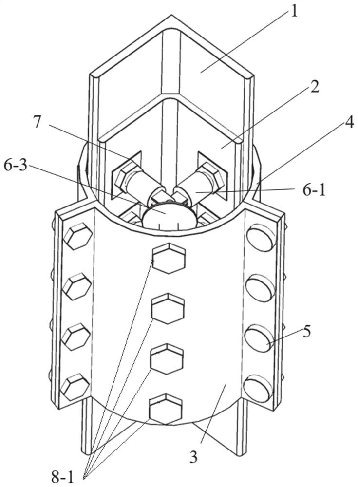
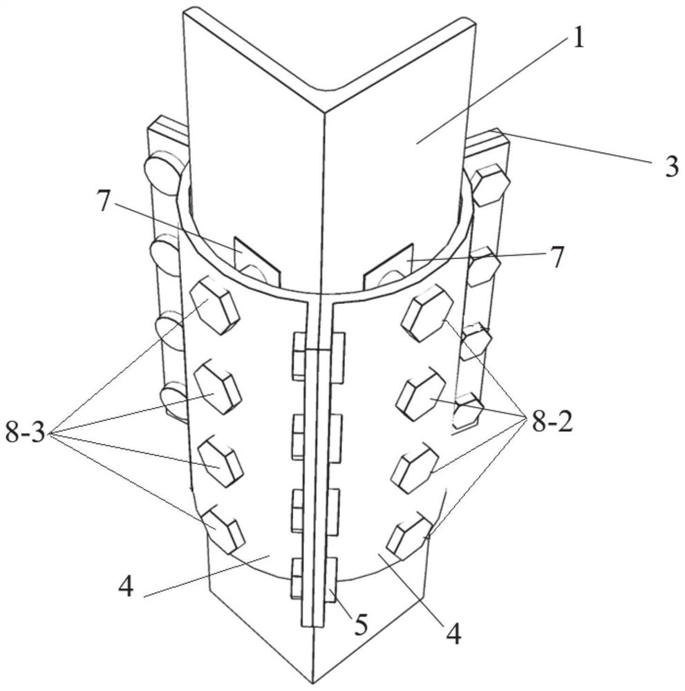
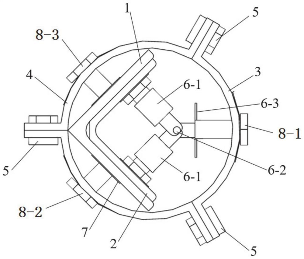
The invention discloses a bolt pressure-bearing embracing type steel angle reinforcing and correcting device for a power transmission tower. The device comprises reinforcing steel angles, hoops and connectors. The reinforcing steel angles are placed on the inner sides of two limbs of a to-be-reinforced steel angle; the axis direction of the reinforcing steel angles is parallel to the to-be-reinforced steel angle; the outer walls of the two limbs of the reinforcing steel angles are attached to the inner wall of the to-be-reinforced steel angle; the hoops are placed on the outer sides of the reinforcing steel angles and the to-be-reinforced steel angle and connected through high-strength bolts; three sets of threaded holes are formed in the side wall of each hoop; the axis of the first set of threaded holes is perpendicular to the axis of the second set of threaded holes; the first set of bolts penetrate through the first set of threaded holes to apply reinforcing force to the outer side of one limb of the to-be-reinforced steel angle; the second set of bolts penetrate through the second set of threaded holes to apply reinforcing force to the outer side of the other limb of the to-be-reinforced steel angle; and the third set of bolts penetrate through the third group of threaded holes to apply reinforcing force to the reinforcing steel angles through the connectors.

Description

technical field [0001] The invention relates to a structure strengthening technology of a power transmission tower, in particular to a bolt pressure-embracing angle steel reinforcement and correction device for a power transmission tower. Background technique [0002] At present, the transmission tower structure itself has insufficient bearing capacity or later damage, which eventually leads to the destruction of components and even the collapse of the transmission tower structure, which seriously affects people's normal production and life, and even seriously affects disaster rescue work. For the angle steel members of transmission towers that have buckled and damaged, although the angle steel members can continue to be used in the case of slight damage, they can only be replaced if they have been deformed, resulting in a large waste of material resources. Therefore, to improve the ability of the power grid to resist natural disasters, the transmission towers should be put i...

Claims


Application Information

Patent Timeline
Patent Type & Authority Applications(China)
IPC IPC(8): E04G23/02E04H12/08
CPCE04G23/0218E04H12/08E04H12/10
Inventor 田利杨萌刘俊才罗贤超王晓阳马震孟祥瑞
Owner SHANDONG UNIV
Learn More