Unlock instant, AI-driven research and patent intelligence for your innovation.

Hydraulic retarder lubricating system

A technology of hydraulic retarder and lubricating system, which is used in hydraulic resistance brakes, lubricating parts, engine lubrication, etc., can solve problems such as retarder not working, unable to obtain effective oil lubrication, bearing damage, etc.

Pending Publication Date: 2021-12-14
吉林省中誉信德科技有限公司
View PDF0 Cites 1 Cited by
  • Summary
  • Abstract
  • Description
  • Claims
  • Application Information

AI Technical Summary

Problems solved by technology

Specifically: when the retarder is working, the oil in the oil storage chamber can flow into the working chamber through pressure, and the bearing can be lubricated; when the retarder stops working, the oil will flow back into the oil storage chamber, leaving only the oil at the bottom of the working chamber There is a small amount of oil, and because the bearing is located in the middle of the working chamber, the residual oil is at the bottom of the working chamber, the bearing cannot be effectively lubricated by the oil, and if it is not lubricated for a long time, the service life of the bearing will be reduced and the bearing will be damaged. Eventually the retarder doesn't work

Method used


Image

  • Hydraulic retarder lubricating system
  • Hydraulic retarder lubricating system
  • Hydraulic retarder lubricating system

Examples


Embodiment 1

[0035] Basic as attached figure 1 And attached figure 2 As shown, a lubricating system for a hydraulic retarder includes a middle casing 11 of the hydraulic retarder and a rear casing 18 of the hydraulic retarder, and a seal is arranged between the middle casing 11 and the rear casing 18 components.

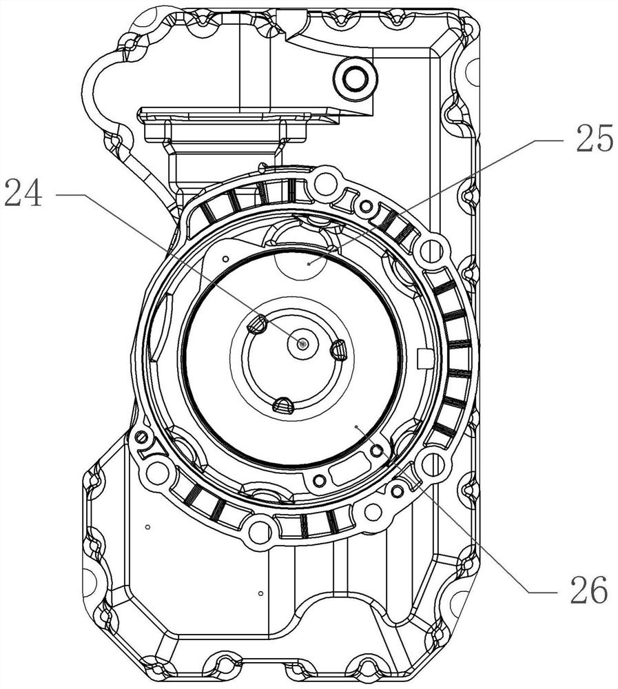
[0036] In this embodiment, a working cavity 26 is integrally formed on the rear casing 18, and the working cavity 26 is circular and grooved. The rear casing 18 is provided with a first oil hole 24 located in the middle of the working cavity 26 and a The second oil hole 25 on the peripheral side of 26, in this embodiment, the positions of the first oil hole 24 and the second oil hole 25 can be changed according to requirements, and the rear housing 18 is integrally formed with a raised cylinder 12, and the raised cylinder 12 There is a penetrating oil inlet hole inside, and the oil inlet hole communicates with the first oil hole 24 .

[0037] In this embodiment, the sealing a...

Embodiment 2

[0045] The difference between the second embodiment and the first embodiment is that it is basically as attached image 3 And attached Figure 4 As shown, the middle housing 11 is provided with an oil return hole 31 communicating with the working chamber 26, and the middle housing 11 is integrally formed with a hollow oil return column 32 with openings at both ends, and the oil return column 32 communicates with the oil return hole 31 .

[0046] In this embodiment, the oil pressure plate 14 is provided with an oil return hole 33 , the metal gasket 16 is provided with a metal gasket oil return hole 34 , and one side of the oil storage chamber is integrally formed with an oil return chamber 35 . The oil return column 32 extends into the oil return chamber 35 through the oil return hole 33 of the oil pressure plate and the oil return hole 34 of the metal gasket, and the oil return column 32 communicates with the oil return chamber 35 . The oil return chamber 35 communicates wit...


PUM


Abstract

The invention belongs to the technical field of hydraulic retarder lubricating equipment, and provides a hydraulic retarder lubricating system. The system comprises a middle shell and a rear shell fixedly connected with the middle shell, and a sealing assembly is fixedly installed between the middle shell and the rear shell. An annular working cavity is formed in the middle shell, and a first oil hole communicated with the working cavity is formed in the middle shell; and an oil storage chamber is arranged on the rear shell and comprises an oil liquid part and an oil storage part, and a lubricating oil storage chamber communicated with the oil liquid part is arranged at one side of the oil liquid part. The lubricating system is simple in structure, and lubrication work of a hydraulic retarder in a non-working state and a working state is achieved.

Description

technical field [0001] The invention belongs to the technical field of lubricating equipment for hydraulic retarders, and in particular relates to a lubricating system for hydraulic retarders. Background technique [0002] Because the rotor inside the working chamber of the retarder rotates with the transmission shaft, as long as the vehicle is running normally, no matter whether the retarder is working or not, the rotor is rotating, and the bearings in the working chamber are in a high-speed (low-speed) rotating state. Specifically: when the retarder is working, the oil in the oil storage chamber can flow into the working chamber through pressure, and the bearing can be lubricated; when the retarder stops working, the oil will flow back into the oil storage chamber, leaving only the oil at the bottom of the working chamber There is a small amount of oil, and because the bearing is located in the middle of the working chamber, the residual oil is at the bottom of the working...

Claims


Application Information

Patent Timeline
IPC IPC(8): F16D57/02F16N7/30F16N39/02F16H57/04
CPCF16D57/02F16N7/30F16N39/02F16H57/0471F16H57/0434F16H57/0421F16H57/0413
Inventor 传海军王键李超伦
Owner 吉林省中誉信德科技有限公司
Features
  • R&D
  • Intellectual Property
  • Life Sciences
  • Materials
  • Tech Scout
  • Unparalleled Data Quality
  • Higher Quality Content
  • 60% Fewer Hallucinations
Learn More