3D visual identification pick-and-place system and method

A visual recognition and 3D technology, applied in image data processing, instrumentation, computing, etc., can solve problems such as large matching errors, lack of visual features, high-speed and high-stability pick-and-place operations, and achieve the effect of improving high precision

Pending Publication Date: 2021-12-14
江西省智能产业技术创新研究院
View PDF0 Cites 1 Cited by
  • Summary
  • Abstract
  • Description
  • Claims
  • Application Information

AI Technical Summary

Problems solved by technology

However, for irregular-shaped industrial products, the lack of visual features is prone to matching difficulties, resulting in large matching errors or

Method used


Image

  • 3D visual identification pick-and-place system and method
  • 3D visual identification pick-and-place system and method
  • 3D visual identification pick-and-place system and method

Examples


Embodiment 1

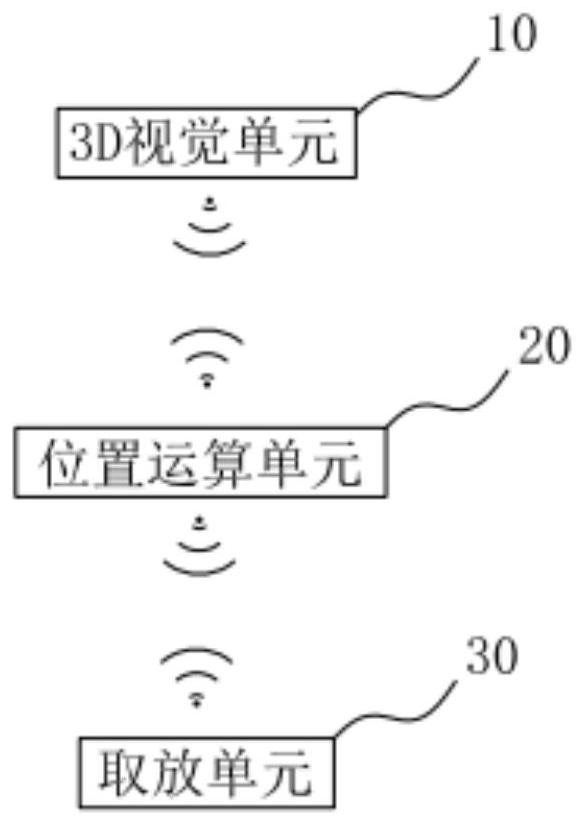
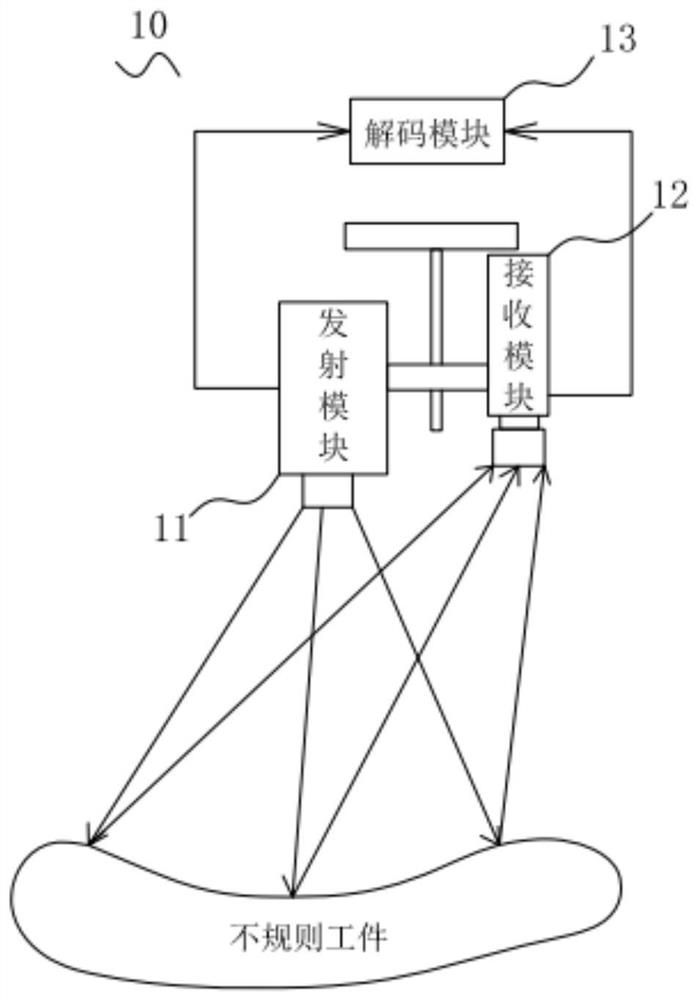
[0044] In Embodiment 1 of the present invention, as figure 1 As shown, a 3D visual recognition pick-and-place system is provided, which is applied to control the grabbing and placement of irregular workpieces. The irregular workpieces involved in the present invention can be 3C electronic products, metal processing parts, etc. Specifically, the system includes a 3D vision unit 10, a pose calculation unit 20, and a pick-and-place unit 30, wherein the 3D vision unit 10 is used to generate the scene point cloud of the identified irregular workpiece, the position The pose calculation unit 20 is used to acquire matching parameters and calculate the pose point cloud of the irregular workpiece, and the pick-and-place unit 30 is used to grab and place the irregular workpiece. In this embodiment, the stereo vision system composed of the 3D vision unit 10 can effectively solve the problem that the current 3D vision system adopts a binocular sensor and uses two cameras to obtain a 3D poi...

Embodiment 2

[0056] In the second embodiment of the present invention, as Image 6 As shown, a 3D visual recognition pick-and-place method is applied to realize the control of irregular workpiece grasping and placement, including the above-mentioned 3D visual recognition pick-and-place system; the 3D visual recognition pick-and-place method includes the following steps:

[0057] S101: The 3D vision unit receives the observed scene image of the irregular workpiece, and reconstructs the scene point cloud of the irregular workpiece based on the scene image;

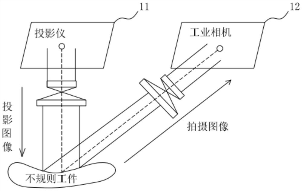
[0058] Wherein, the scene point cloud is the detailed point cloud data of the irregular workpiece, including the position and posture of the irregular workpiece; specifically, through the stereo vision system of this embodiment, that is, the coded pattern is projected by the projector, and the industrial The camera shoots the irregular workpiece and the captured image is sent to the host computer. The host computer processes the image an...

Embodiment 3

[0069] In the third embodiment of the present invention, as Figure 7 As shown, a 3D visual recognition pick-and-place method is applied to realize the control of irregular workpiece grasping and placement. The method of this embodiment is different from the method of Embodiment 2 in that: the 3D vision unit After receiving the observed scene image of the irregular workpiece, and reconstructing the scene point cloud of the irregular workpiece based on the scene image, the method further includes:

[0070] Filtering is performed on the scene point cloud.


PUM


Abstract

The invention provides a 3D visual identification pick-and-place system and method, and belongs to the technical field of visual guidance robots. The system comprises a 3D vision unit, a pose operation unit and a pick-and-place unit which are in communication connection; the 3D vision unit projects a coding pattern, shoots irregular workpieces, acquires an image, and decodes the coding pattern by using calibrated parameters to obtain scene point clouds; a template library module creates template point clouds of the irregular workpieces under different poses; the scene point clouds and the template point clouds are matched to obtain matching parameters; the pose operation module calculates a grabbing pose and a placing pose according to the input matching parameters, so that the pick-and-place unit grabs and places the irregular workpieces. According to the system and the method, the problems of large matching error and even matching failure caused by difficult matching of the irregular workpieces due to lack of visual features are effectively solved, so that the high-precision, high-speed and high-stability taking and placing operation of the irregular workpieces is improved.

Description

technical field [0001] The invention belongs to the technical field of vision-guided robots, and in particular relates to a 3D visual recognition pick-and-place system and method. Background technique [0002] With the development of technology, robots will gradually replace humans to complete some simple, repetitive, and low-intellectual work. Vision-guided robot grasping technology is more and more widely used in industry, and the application scenarios are becoming more and more abundant, such as in industrial processes such as machine assembly, parts sorting, and loading and unloading classification. The application of traditional vision-guided robot grasping mainly focuses on the grasping of target objects on a fixed plane based on 2D vision detection. 2D vision detection methods can provide limited information on the position and orientation of parts, and usually only limit the parts to a fixed measurement depth. on the detection. However, when the grasped irregular o...

Claims


Application Information

Patent Timeline
IPC IPC(8): G06T7/73
CPCG06T7/73G06T2207/10028G06T2207/30164
Inventor 聂志华曹燕杰
Owner 江西省智能产业技术创新研究院
Why Eureka
Try Eureka