
A broadband millimeter wave signal analog-to-digital conversion method and system

A signal conversion and millimeter wave technology, applied in the field of microwave photonics, can solve the problems of small analog bandwidth of electrical pulses, clock asynchrony, damage, etc., to achieve the effect of improving high precision, suppressing nonlinearity, and large instantaneous bandwidth

Active Publication Date: 2022-06-28
PEKING UNIV +1
View PDF7 Cites 0 Cited by
  • Summary
  • Abstract
  • Description
  • Claims
  • Application Information

AI Technical Summary

Problems solved by technology

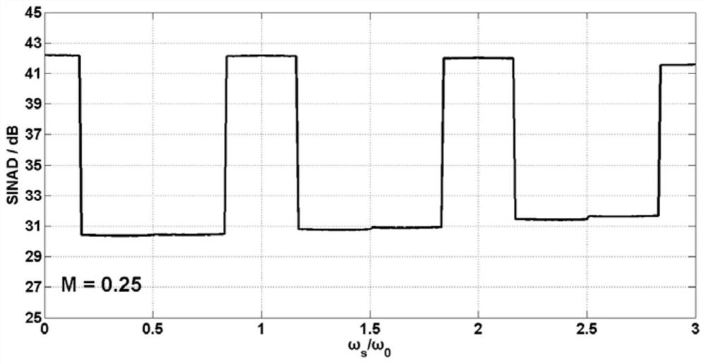
The disadvantage of this scheme is that the shape of the electrical pulse is destroyed due to the small analog bandwidth, and there is no synchronization between the optical pulse and the clock of the quantizer, so even if a dual-output electro-optic intensity modulator is used in the traditional method, it cannot Effective mathematical algorithms are used to overcome the nonlinearity introduced by the electro-optical intensity modulator, so that the spurious-free dynamic range (SFDR) and signal-to-noise-to-spur ratio (SINAD) of the entire system are significantly reduced after the electro-optical-electrical conversion, reducing the The analog-to-digital conversion accuracy of the entire system

Method used


Image

  • A broadband millimeter wave signal analog-to-digital conversion method and system
  • A broadband millimeter wave signal analog-to-digital conversion method and system
  • A broadband millimeter wave signal analog-to-digital conversion method and system

Examples


Embodiment Construction

[0029] The solution of the present invention will be described in further detail below with reference to the accompanying drawings.

[0030] The scheme principle of the present invention is as follows figure 1 shown. The stable high-power laser outputs continuous seed light, which is injected into an optical comb modulator to generate optical pulses. The optical comb modulator is composed of a lithium niobate phase modulator placed in a Fabry-Perot cavity. The repetition frequency of the optical pulse output by the optical comb modulator is equal to the frequency of the output signal of the tunable frequency synthesizer controlling its electrical port, so it can be adjusted within a certain range. Due to the insertion loss of the optical comb modulator, its output optical signal needs to be amplified by a single-stage erbium-doped fiber amplifier. Since the erbium-doped fiber amplifier will introduce additional noise while amplifying the optical signal, and the optical pulse g...


PUM


Abstract

The invention discloses a broadband millimeter wave signal analog-to-digital conversion method and system. The method is as follows: 1) the optical pulse is input to the optical port of the dual-output electro-optic intensity modulator; the electrical port of the dual-output electro-optical intensity modulator is used to receive the millimeter-wave signal to be converted; wherein, the frequency range of the millimeter-wave signal is [f 1 , f 2 ], light pulse frequency f 0 Satisfy 2) Convert the modulated optical signals output by the two arms of the dual-output electro-optical intensity modulator back into electrical signals v 1 (t), v 2 (t); then check mark v 1 (t), v 2 (t) After performing low-pass filtering and quantization respectively, the signal V 1 (t), V 2 (t) and input digital signal processing unit; 3) digital signal processing unit according to signal V 1 (t), V 2 (t) Calculate and obtain the converted digital signal of the millimeter wave signal to be converted.

Description

technical field [0001] The invention relates to a method and a system for realizing analog-to-digital conversion of broadband millimeter-wave signals through optical auxiliary means based on algorithm optimization. The mathematical expression of the analog electrical signal to be converted from analog to digital after electrical-optical-electrical conversion is obtained by derivation, and then the optimal algorithm suitable for the system and the corresponding operating frequency range are obtained through analysis and calculation. The repetition frequency of the optical pulse in the system is tuned according to the frequency of the analog electrical signal, so that the frequency of the millimeter wave signal falls within the working range. By applying the optimal optical frequency comb repetition frequency and applying the derived algorithm, the broadband millimeter wave signal can be converted into a baseband digital signal with high precision after passing through the entir...

Claims


Application Information

Patent Timeline
Patent Type & Authority Patents(China)
IPC IPC(8): H03M1/12
CPCH03M1/1245
Inventor 郭锐雷鹏张宸博尹卿朱立新陈章渊
Owner PEKING UNIV
Learn More