
Driving assembly of crow bar bending bicycle

A technology for driving components and bicycles, which is applied to vehicle components, rider driving, transportation and packaging, etc. It can solve the problems of pedals not being able to rotate circularly and not being labor-saving enough to achieve reasonable structural layout, avoid conflicts between parts, and solve bending angles oversized effect

Active Publication Date: 2021-12-17
慈溪市神驹节能科技有限公司
View PDF7 Cites 0 Cited by
  • Summary
  • Abstract
  • Description
  • Claims
  • Application Information

AI Technical Summary

Problems solved by technology

However, the pedals cannot rotate in a circle, and need to be relearned or adapted to the new riding mode, and it is not labor-saving enough

Method used


Image

  • Driving assembly of crow bar bending bicycle
  • Driving assembly of crow bar bending bicycle
  • Driving assembly of crow bar bending bicycle

Examples


Embodiment 1

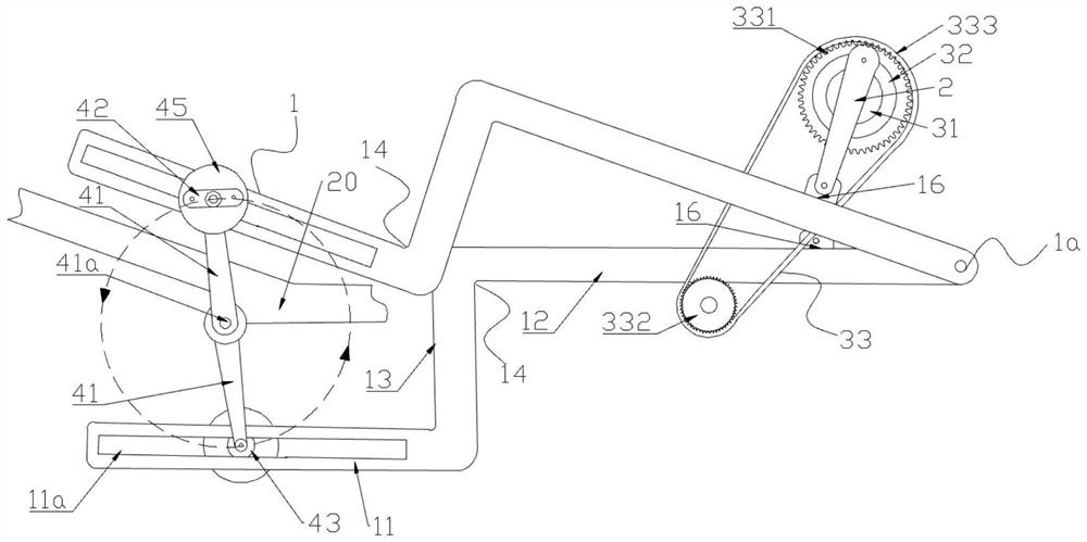
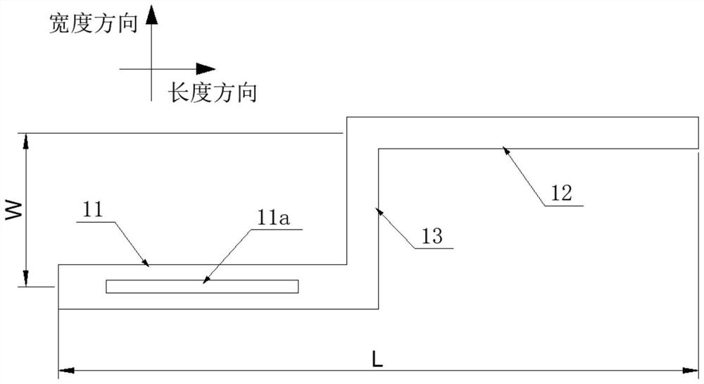
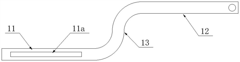
[0042] Such as Figure 1-3b , 8-9, shown in 12, the present invention provides the driving assembly of crow bar crank bicycle, comprises crow bar 1, crank bar 2, flywheel crank mechanism 3 and pedal assembly 4, and flywheel crank mechanism 3 and bicycle Rear wheel 5 transmissions are connected, pedal assembly 4 comprises rotating rod 41, pedal 42, and the first end of rotating rod 41 is rotatably hinged on the vehicle frame 20, and pedal 42 is installed on the second end of rotating rod 41, and crowbar 1 includes a first crowbar 11 and a second crowbar 12 that are not on the same straight line, and the inner ends of the first crowbar 11 and the second crowbar 12 are connected by a first connecting section 13 to form a complete crowbar 1, the first crowbar 1 The crowbar 11 , the second crowbar 12 and the first connecting section 13 can be integrally formed, or can be manufactured separately and assembled to form a whole, preferably the former.

[0043] Such as figure 1 , 2a ...


PUM


Abstract

The invention discloses a driving assembly of a crow bar bending bicycle, a first crow bar and a second crow bar are arranged to be not on the same straight line so as to avoid parts on a rear wheel; a connecting piece on the pedal assembly is movably arranged in the sliding rail of the first crow bar, the second crow bar is rotatably hinged to the frame, when the pedal drives a rotating rod to rotate around a rotating shaft of the rotating rod by 360 degrees, the connecting piece rotates along with the rotating rod to drive the second crow bar to swing in a reciprocating mode along a hinged shaft of the second crow bar, and the rear wheel is driven through the curved bar on the second crow bar under the transmission effect of a flywheel driving mechanism. The torque is transmitted to the rear wheel through the crank lever by means of the flywheel crank mechanism, people do not need to relearn and adapt to the riding way, and the purposes of quicker speed and more labor saving can be achieved.

Description

technical field [0001] The invention relates to the technical field of bicycle driving mechanisms, in particular to a driving assembly of a crowbar cranking bicycle. Background technique [0002] Traditional bicycle is to connect pedal lever by pedal, and pedal lever connects big sprocket, and big sprocket is connected with the little flywheel on the rear wheel by chain, and little flywheel drives rear wheel to rotate, and bicycle can be walked. Since the bicycle is powered by the crank pedal, and is limited by the height of the bicycle frame and the range of motion of the human leg, the crank length of the bicycle is limited, and it is not labor-saving when riding. The only way to increase the pedaling frequency is to reduce The weight of the body is used to increase the speed, and it is easy to get tired during long-distance riding. [0003] In order to solve the above problems, some improvements to bicycles have been made on the market, making it more labor-saving when r...

Claims


Application Information

Patent Timeline
IPC IPC(8): B62M1/26B62M1/28
CPCB62M1/26B62M1/28
Inventor 孙梦园孙凤枝施央君
Owner 慈溪市神驹节能科技有限公司
Features
  • Generate Ideas
  • Intellectual Property
  • Life Sciences
  • Materials
  • Tech Scout
  • Unparalleled Data Quality
  • Higher Quality Content
  • 60% Fewer Hallucinations
Learn More