
Air-gas linkage control device with function of controlling gas by air

A technology of gas function and wind, which is applied in the field of wind-air linkage control devices, can solve the problems of high operating threshold, strict requirements for sensitive response of fans, adverse effects of fan service life, etc., and achieve the effect of lowering the operating threshold and high ignition reliability

Pending Publication Date: 2021-12-17
ANHUI HANSUM INSTR EQUIP
View PDF0 Cites 0 Cited by
  • Summary
  • Abstract
  • Description
  • Claims
  • Application Information

AI Technical Summary

Problems solved by technology

In the case of active damper follow-up of the valve, once the valve is slightly adjusted, the fan at the damper must constantly change the speed frequently to correspond to different input wind forces. This not only puts strict requirements on the sensitive response of the fan, but also frequently accelerates and decelerates It also has an adverse effect on the service life of the fan
In addition, the above-mentioned method of "controlling the wind with air" often requires experienced chefs to fire the fire. The air volume and the air intake of the damper are at the optimum point, and the operating threshold is extremely high, which obviously seriously restricts the normal development of the stove industry and needs to be solved urgently

Method used


Image

  • Air-gas linkage control device with function of controlling gas by air
  • Air-gas linkage control device with function of controlling gas by air
  • Air-gas linkage control device with function of controlling gas by air

Examples


Embodiment Construction

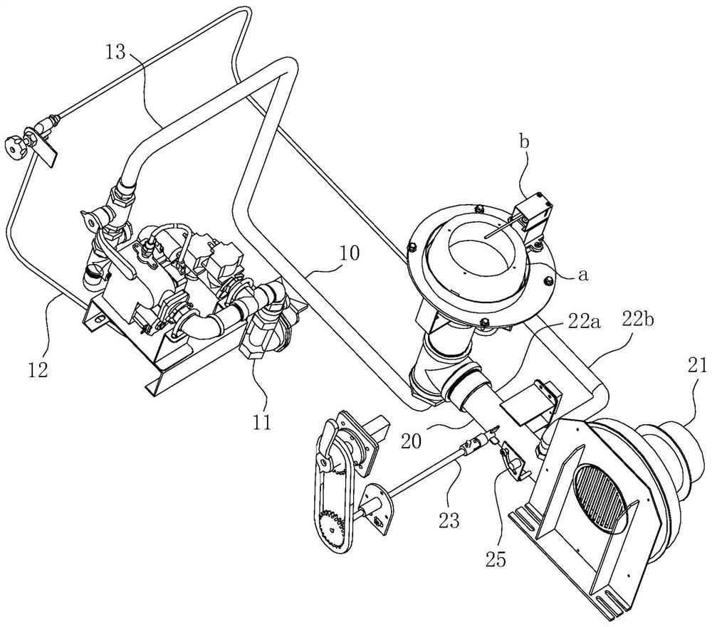
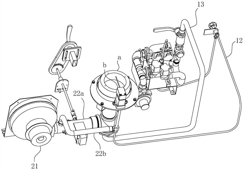
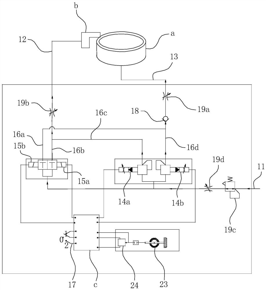
[0046] For ease of understanding, here, taking the application embodiment of the one-way ball valve 18 as an example, the specific structure and working method of the present invention are further described as follows:

[0047] The concrete implementation structure of the present invention can refer to Figure 1-9 As shown, its main structure includes two major components: the air path module 10 and the air path module 20 . Among them: the gas path module 10 includes an air intake path 11 connected to the gas source, a main gas control module, a backup gas control module, a control switch 17, a one-way ball valve 18, a main fire regulating valve 19a, an open fire regulating valve 19b, Gas pressure stabilizing valve 19c and throttle valve 19d. The air path module 20 mainly includes a wind pressure sampling pipe, an air inlet for an open fire, that is, an air inlet of the second parallel air path 22b, a front damper 25, and a damper 23 arranged in sequence from front to back. ...


PUM


Abstract

The invention belongs to the technical field of commercial cooking ranges, and particularly relates to an air-gas linkage control device with a function of controlling gas by air. The device comprises an gas path module and an air path module, and is characterized in that the gas path module comprises a gas inlet path communicating with a gas source, an electromagnetic proportional valve used for controlling the gas inlet amount of the gas inlet path is arranged at the gas inlet path, the air path module comprises a draught fan, the air outlet end of the draught fan communicates with an air inlet path, an adjusting air door is arranged on the air inlet path and driven by an air door shaft so as to adjust the air inlet amount of the air inlet path, an angle sensor used for monitoring the rotating angle of the air door shaft is arranged beside the air door shaft, the signal output end of the angle sensor is electrically connected with the signal input end of a controller, and the signal output end of the controller is electrically connected with the electromagnetic proportional valve. By means of the mode of controlling gas by air, the device has the advantages of being low in operation threshold and high in ignition reliability, and the ignition efficiency and the service life of a cooking range can be effectively guaranteed accordingly.

Description

technical field [0001] The invention belongs to the technical field of commercial stoves, and in particular relates to an air-air linkage control device with the function of air-controlling air. Background technique [0002] The gas path of traditional commercial stoves is mostly a vertical hard pipe connected to the gas path and a horizontal hard pipe connected to the air path to form a T-shaped pipe. There is an air inlet valve at the entrance of the vertical hard pipe, and a branch of gas is used to connect to the flameout protection electromagnetic switch valve. The flameout protection electromagnetic switch valve is divided into two branches: one path passes through the constant flame electromagnetic proportional valve. Even with the normal open flame burner, all the way is connected to the main fire burner through the main fire electromagnetic proportional valve. When working, close the power switch and start the fan; on the one hand, the ignition controller opens the...

Claims


Application Information

Patent Timeline
IPC IPC(8): F24C3/12F23N1/02
CPCF24C3/126F23N1/025
Inventor 夏光超
Owner ANHUI HANSUM INSTR EQUIP
Learn More