
Flashover test device and method in gas insulated power equipment under temperature gradient working condition

A technology of gas insulation and temperature gradient, which is applied in the direction of measuring devices, testing dielectric strength, and measuring electricity, can solve the problems of less development, low detection accuracy, and the inability of temperature sensors to directly measure the temperature of epoxy post insulators.

Active Publication Date: 2021-12-17
HUNAN UNIV
View PDF7 Cites 1 Cited by
  • Summary
  • Abstract
  • Description
  • Claims
  • Application Information

AI Technical Summary

Problems solved by technology

[0004] Some scholars have designed flashover experiment schemes at different temperatures, and placed high-temperature ceramic heating plates at the bottom of the ground electrode to realize the flashover device under the temperature gradient working condition of "ground electrode-high voltage electrode". Conditions - high voltage side (high temperature) - ground electrode side (low temperature) working conditions are less developed
At the same time, the temperature sensor in this scheme cannot effectively and directly measure the temperature of the epoxy post insulator, and the detection accuracy is low
In addition, some people have learned to use the oil bath heating method to carry out temperature gradient tests, but the heating rod is generally made of metal, which will inevitably be affected by the high voltage at the electrode

Method used


Image

  • Flashover test device and method in gas insulated power equipment under temperature gradient working condition
  • Flashover test device and method in gas insulated power equipment under temperature gradient working condition
  • Flashover test device and method in gas insulated power equipment under temperature gradient working condition

Examples


Embodiment Construction

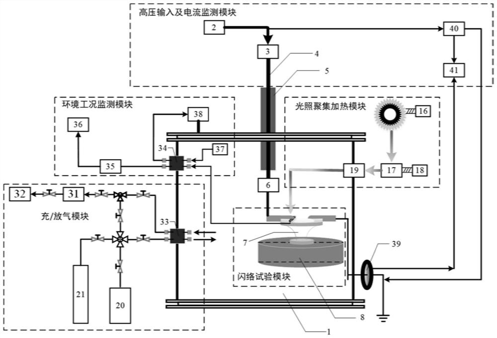
[0052] Embodiments of the present invention are described in detail below, examples of which are shown in the drawings, wherein the same or similar reference numerals designate the same or similar elements or elements having the same or similar functions throughout. The embodiments described below by referring to the figures are exemplary and are intended to explain the present invention and should not be construed as limiting the present invention.

[0053] The apparatus and method for flashover testing under temperature gradient conditions in gas-insulated power equipment according to embodiments of the present invention will be described below with reference to the accompanying drawings.

[0054] First, a flashover test device under temperature gradient conditions in gas-insulated power equipment according to an embodiment of the present invention will be described with reference to the accompanying drawings.

[0055] figure 1 It is a structural schematic diagram of a flas...


PUM


Abstract

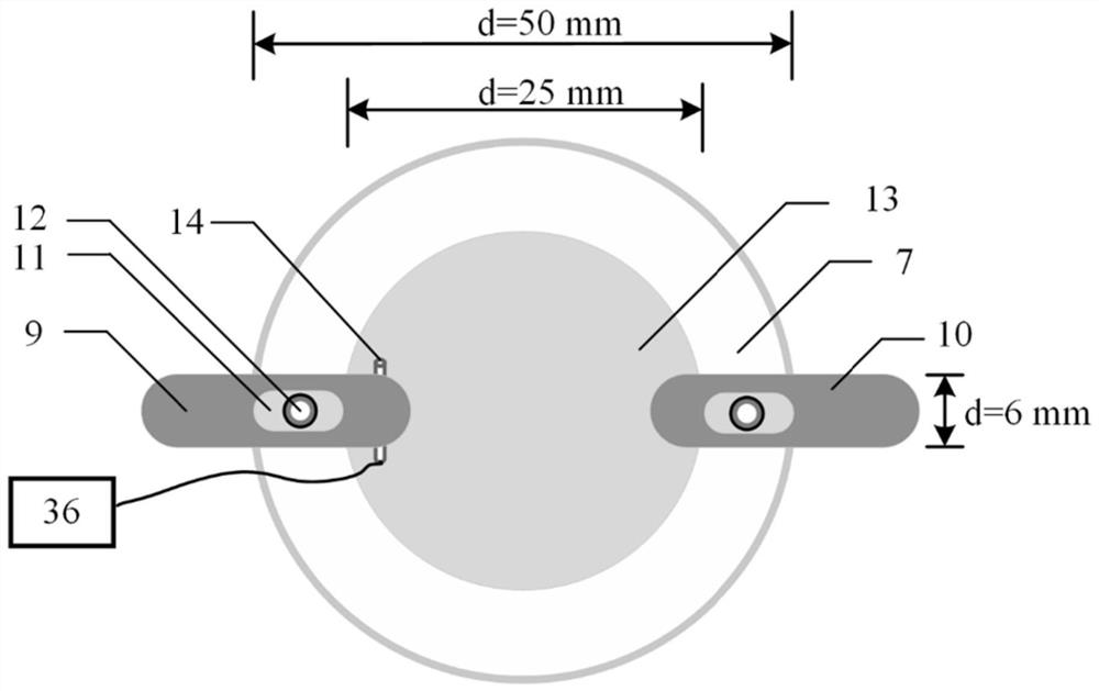
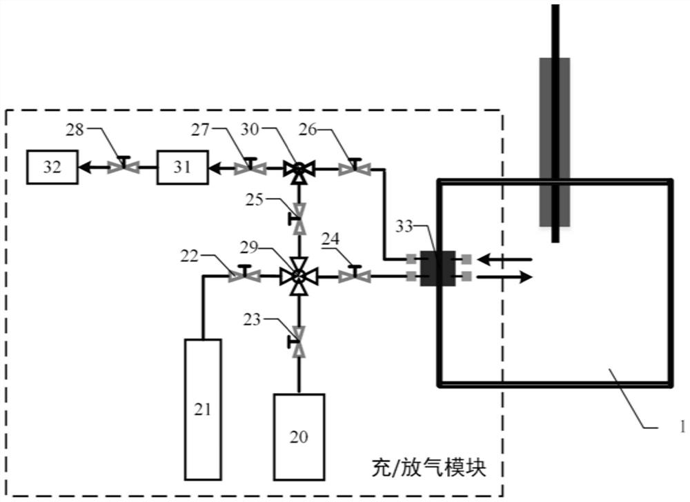
The invention discloses a flashover test device and a flashover test method in gas insulated power equipment under a temperature gradient working condition. The flashover test device comprises a flashover test module used for providing a flashover platform base for placing a high-voltage flashover electrode, a low-voltage flashover electrode and an insulated sample; an inflation and deflation module used for providing buffer gas and environment-friendly insulating gas for a gas insulation discharge test cavity; an illumination gathering heating module used for emitting visible light to heat the high-voltage flashover electrode; an environment working condition monitoring module used for monitoring the temperature of the high-voltage flashover electrode and the environment temperature and humidity; and a high-voltage input and current detection module used for outputting high voltage to act on the heated high-voltage flashover electrode, so that the flashover electrode has a flashover phenomenon, and the current of the flashover electrode is detected. The flashover test device can accurately discuss flashover tests under environment-friendly insulating gases with different temperature gradients, different gas pressures and different proportions, and can research the influence of different environments on flashover voltage.

Description

technical field [0001] The invention relates to the technical field of electrical insulation and discharge of power equipment, in particular to a flashover test device and method under temperature gradient conditions in gas-insulated power equipment. Background technique [0002] Compared with traditional overhead transmission lines, gas-insulated enclosed combined electrical appliances (GIS) and gas-insulated transmission pipelines (GIL) are widely used due to their high reliability, small footprint, convenient operation and maintenance, and low external interference. in the transmission line. Gas-insulated high-voltage electrical equipment such as gas-insulated high-voltage electrical appliances (GIS) and gas-insulated transmission pipelines are prone to high field strength during operation, which will lead to surface flashover accidents at the interface between insulating gas and epoxy resin insulating materials or EPDM materials , is a relatively common insulation fault...

Claims


Application Information

Patent Timeline
IPC IPC(8): G01R31/12
CPCG01R31/1254
Inventor 汪沨刘杰甘辉钟理鹏陈赦海彬聂佳林晓青
Owner HUNAN UNIV
Learn More