
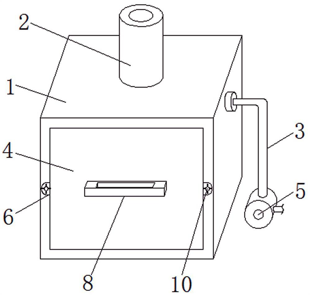
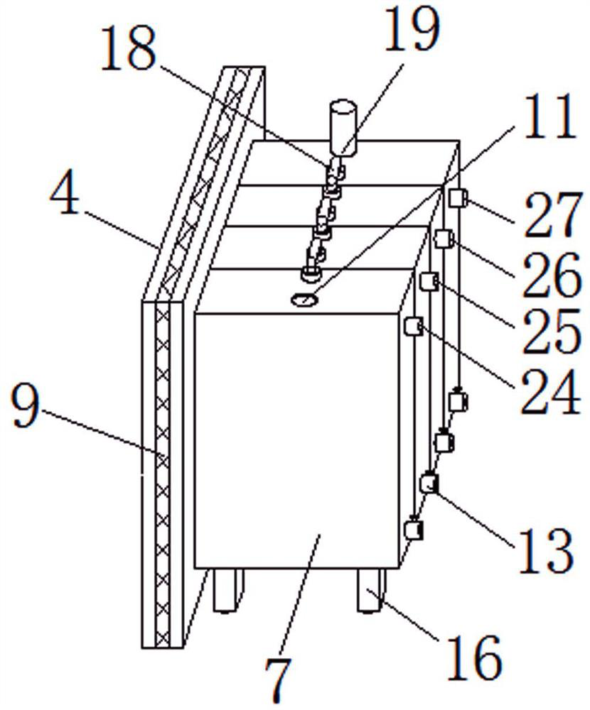
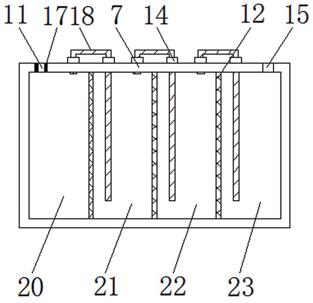
A boiler room waste gas recovery device

A waste gas recovery and boiler room technology, applied in the direction of reducing greenhouse gases, climate sustainability, air quality improvement, etc., can solve the problems of unable to take out the treatment box, slow down the speed of the treatment box, and increase the labor intensity of supervisors, so as to reduce the Labor intensity, improved functionality, improved convenience

Active Publication Date: 2022-07-05
CHINA PETROLEUM & CHEM CORP +2
View PDF7 Cites 0 Cited by
  • Summary
  • Abstract
  • Description
  • Claims
  • Application Information

AI Technical Summary

Problems solved by technology

[0003] At present, there are still some deficiencies in the existing boiler room exhaust gas recovery device, for example; the existing boiler room exhaust gas recovery device cannot classify and detect the treated exhaust gas, and cannot directly communicate the detected reception to supervisors remotely , the supervisors cannot directly understand the link problems of waste gas treatment, which reduces the functionality of the waste gas recovery device during use, and the existing boiler room waste gas recovery device cannot allow the supervisors to directly take out the treatment box from the inside of the recovery box, reducing the It slows down the cleaning speed of the treatment box, increases the labor intensity of the supervisors during the cleaning process, and reduces the convenience of the waste gas recovery device cleaning process

Method used


Image

  • A boiler room waste gas recovery device
  • A boiler room waste gas recovery device
  • A boiler room waste gas recovery device

Examples


Embodiment Construction

[0024] The technical solutions in the embodiments of the present invention will be clearly and completely described below with reference to the accompanying drawings in the embodiments of the present invention. Obviously, the described embodiments are only a part of the embodiments of the present invention, but not all of the embodiments.

[0025] In the description of the present invention, it should be understood that the terms "upper", "lower", "front", "rear", "left", "right", "top", "bottom", "inside", " The orientation or positional relationship indicated by "outside" is based on the orientation or positional relationship shown in the accompanying drawings, and is only for the convenience of describing the present invention and simplifying the description, rather than indicating or implying that the indicated device or element must have a specific orientation, so as to The specific orientation configuration and operation are therefore not to be construed as limitations of...


PUM


Abstract

The invention discloses a waste gas recovery device in a boiler room. Its structure includes a recovery box body. An exhaust pipe, an air hose and a sealing plate are arranged on the recovery box body. The exhaust pipe is sealed and connected to the recovery box. The upper end of the box body, one end of the gas delivery hose is located at the right end of the recovery box body, the sealing plate is embedded in the inside of the front of the recovery box body, and the other end of the gas delivery hose is sealed and connected On the upper end of the blower; the sealing plate is provided with a connecting plate, a processing box, a pull handle and a sealing ring, the connecting plate is welded to the left and right sides of the sealing plate, and the processing box is fixedly connected to the sealing plate The right end of the pull handle is fixedly connected to the front of the sealing plate. The invention realizes the classification and detection of the treated waste gas, and directly and remotely communicates the detection reception to the supervisors, which facilitates the supervisors to directly understand the link problems of the waste gas treatment, and improves the functionality of the waste gas recovery device during the use process.

Description

technical field [0001] The invention relates to the technical field of waste gas recovery, in particular to a boiler room waste gas recovery device. Background technique [0002] According to Patent No. 201820522023.2, an exhaust gas recovery device in a boiler room includes a treatment chamber, a blowing port, a large particle filter chamber, a micro particle filter chamber, a biological adsorption layer, an exhaust port and a drawing compartment. The air outlet is provided, the inside of the treatment chamber is provided with the particle filter chamber, the micro particle filter chamber and the biological adsorption layer from top to bottom, and the bottom of the large particle filter chamber and the micro particle filter chamber are provided with the In the pull-out compartment, the exhaust port is provided on the left side of the bioadsorption layer, a drain port is provided on the right side of the bioadsorption layer, and a valve is installed at the drain port. The u...

Claims


Application Information

Patent Timeline
Patent Type & Authority Patents(China)
IPC IPC(8): B01D53/30B01D53/52B01D53/56B01D53/62B01D47/02
CPCB01D53/30B01D53/62B01D53/56B01D53/52B01D47/02Y02A50/20
Inventor 姚日远宋志刚史正清戴宝萍何铁王佩德鲍依福
Owner CHINA PETROLEUM & CHEM CORP
Learn More