
Rapid aerial launching box device

A technology of air launch and launch box, which is applied in the direction of launch/drag transmission device, etc., which can solve the problems of not being able to meet the needs of use, and achieve the effect of light weight, large quantity, and rapid deployment

Pending Publication Date: 2021-12-21
沈阳天晴航空航天科技有限公司
View PDF0 Cites 0 Cited by
  • Summary
  • Abstract
  • Description
  • Claims
  • Application Information

AI Technical Summary

Problems solved by technology

There are many ways to launch UAVs, such as taxiing takeoff, rocket-assisted launch, catapult takeoff, hand-throwing launch, vertical takeoff, etc. With the development of aviation technology, UAV-related launch technologies are becoming more and more mature. And the scope is becoming wider and wider, from civilian to military use, from aerial photography, cargo transportation to disaster area survey, enemy situation detection and target strike, the load and equipment required for the task have become increasingly sophisticated and miniaturized, and the task requirements are also becoming more intensive and fast. Response and other directions are developing, which puts forward higher requirements for the high integration, portability and rapid deployment capability of the launch device. The traditional UAV launch form obviously cannot meet such stringent requirements, especially for unmanned aerial vehicles. The given space of the folding envelope of the aircraft is relatively compact, and the projects that need to be quickly deployed to the designated airspace and quickly launch multiple sorties of drone operations cannot meet the needs of use

Method used


Image

  • Rapid aerial launching box device
  • Rapid aerial launching box device
  • Rapid aerial launching box device

Examples


Embodiment Construction

[0014] In order to understand the above-mentioned purpose, features and advantages of the present invention more clearly, the present invention will be further described in detail below in conjunction with specific embodiments. It should be noted that, in the case of no conflict, the embodiments of the present application and the features in the embodiments can be combined with each other.

[0015] In the following description, many specific details are set forth in order to fully understand the present invention. However, the present invention can also be implemented in other ways than described here. Therefore, the protection scope of the present invention is not limited by the specific implementation disclosed below. Example limitations.

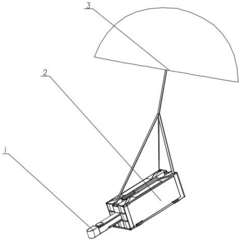
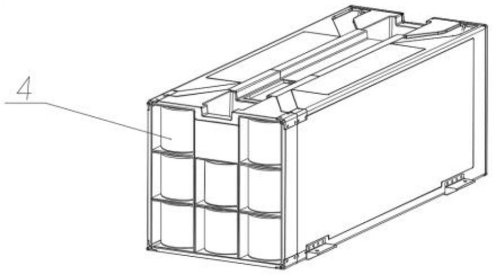
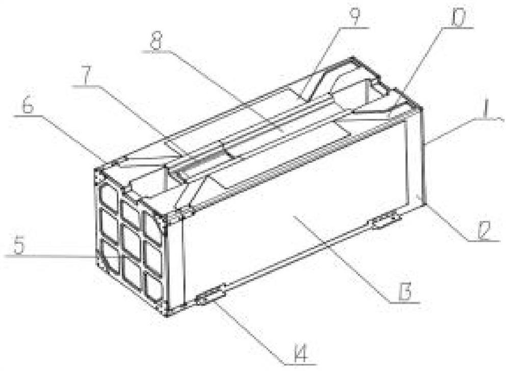
[0016] The present invention provides a technical solution: a rapid air launch box device, including a launch box 12, characterized in that: a number of air launch box devices 2 are evenly distributed in the inner cavity of the launch box...


PUM


Abstract

The invention discloses a rapid aerial launch box device which comprises a launch box, a plurality of aerial launch box devices are evenly distributed in the inner cavity of the launch box, an equipment compartment is arranged on the launch box, a parachute compartment is arranged in the equipment compartment, a gas generator is electrically connected with a controller, and the controller is electrically connected with a wireless signal transmitting device. The device is small in size, light in weight and convenient to carry, the number of carried unmanned aerial vehicles is large, the unmanned aerial vehicles work rapidly, and meanwhile the device has the electric heating function. The device can be carried by various aerial carriers to be thrown under the complex airspace condition, and the front opening cover is thrown out and separated under the action of an initiating explosive device. The device is fully automatically controlled after throwing, the brake parachute is automatically opened to stabilize the posture of the device, catapults in the device automatically work to rapidly eject the multiple unmanned aerial vehicles out of the barrel, rapid deployment to a required region is achieved, and then the pain points of the industries are effectively solved.

Description

technical field [0001] The invention is applied in the technical field of unmanned aerial vehicles, and is specifically a rapid aerial launch box device. Background technique [0002] The launch of UAVs refers to the process in which UAVs reach a certain height and speed in the air in a certain take-off place and in a certain way. It is often considered to be one of the most difficult and critical stages in the combat application of UAVs. , which directly affects the maneuverability, regional adaptability, reusability and survivability of UAV systems and other combat technical indicators and requirements. There are many ways to launch UAVs, such as taxiing takeoff, rocket-assisted launch, catapult takeoff, hand-throwing launch, vertical takeoff, etc. With the development of aviation technology, UAV-related launch technologies are becoming more and more mature. And the scope is becoming wider and wider, from civilian to military use, from aerial photography, cargo transporta...

Claims


Application Information

Patent Timeline
Patent Type & Authority Applications(China)
IPC IPC(8): B64F1/06
CPCB64F1/06
Inventor 贺军
Owner 沈阳天晴航空航天科技有限公司
Learn More