
Flue and boiler

A flue and boiler technology, applied in the field of flue, can solve the problems of high replacement cost, slag splashing, violent converter reaction, etc., and achieve the effect of simple structure, convenient replacement and convenient operation

Pending Publication Date: 2021-12-21
WISDRI ENG & RES INC LTD
View PDF0 Cites 2 Cited by
  • Summary
  • Abstract
  • Description
  • Claims
  • Application Information

AI Technical Summary

Problems solved by technology

Due to the large amount of high-temperature flue gas generated during the converter blowing process, the flue gas temperature is usually as high as 2000 ° C, and the reaction in the converter is intense, and there is a risk of slag splashing, and the flue at the furnace mouth is the closest part to the converter except for the skirt. , the flue at the furnace mouth is more susceptible to the influence of the converter, resulting in a shorter service life of the flue at the furnace mouth, and it needs to be replaced after one to two years
In addition, the bottom of the flue at the furnace mouth section is the closest to the furnace mouth of the converter, which is more prone to water leakage, damage, etc., and regular repair welding operations or replacements are required; however, due to the narrow space of the furnace mouth section, only the bottom of the furnace mouth section flue It is inconvenient to carry out maintenance or replacement. In the prior art, the method of replacing the entire flue at the mouth of the furnace is usually adopted, but this method is time-consuming and laborious, and it cannot be replaced in sections according to the damage or water leakage of the flue, and the replacement cost higher

Method used


Image

  • Flue and boiler
  • Flue and boiler
  • Flue and boiler

Examples


Embodiment 1

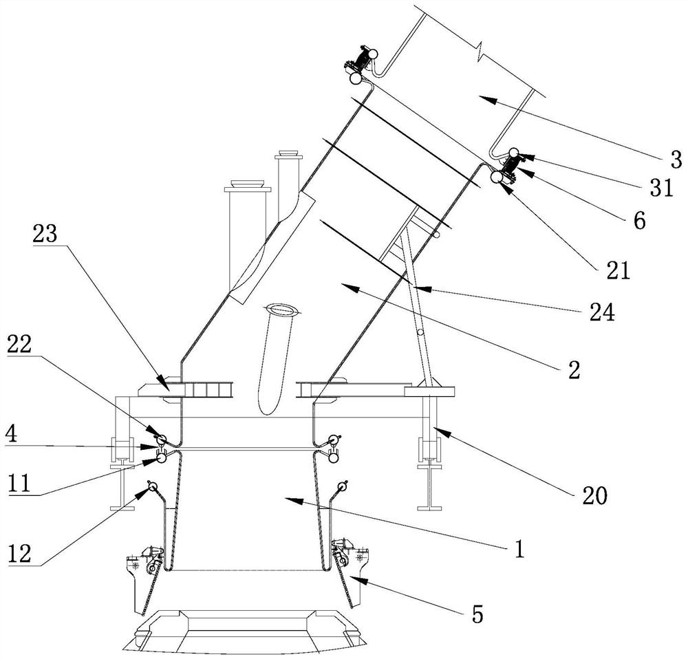
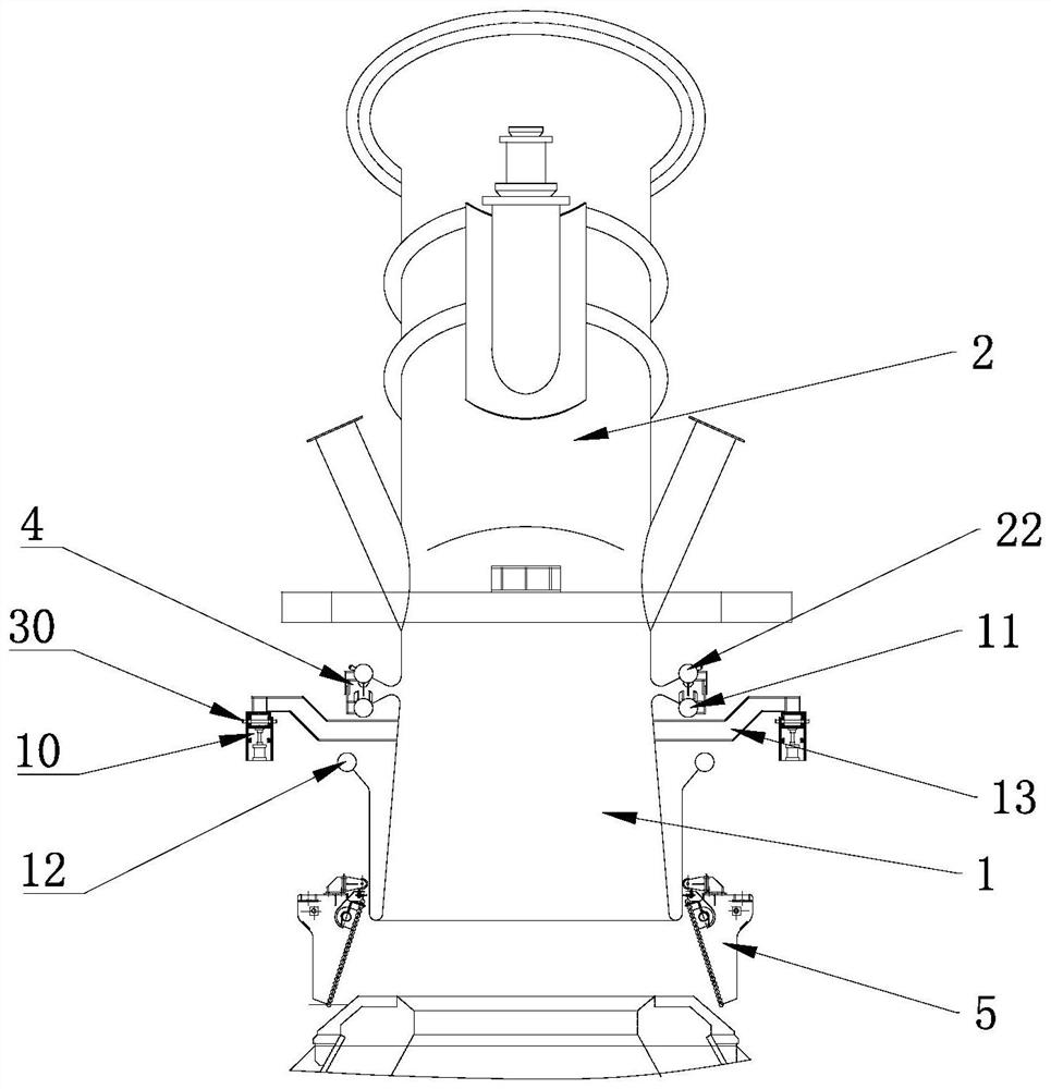
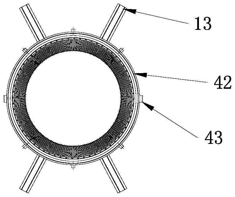
[0030] refer to Figure 1 to Figure 6 As shown, as a preferred embodiment of the present invention, a flue is provided, including a furnace mouth section flue and a main flue 3, the furnace mouth section flue is segmented on the vertical section, and is divided into a furnace mouth fixed section flue Road 1 and flue 2 of the moving section of the furnace mouth. During steelmaking, a large amount of waste gas and dust overflow from the converter mouth. First, the waste gas and dust are collected by the movable fume hood 5, and then enter the dust removal system and recovery system through the flue above the movable fume hood 5. In this embodiment, the direction of the fixed-section flue 1 in the fixed use state is used as the description direction, that is, the side facing the ground is the bottom side, and the other side away from the bottom side is the top side, which are located at the same time. On the elevation and perpendicular to the top and bottom sides are the front a...

Embodiment 2

[0040] This embodiment provides a boiler, preferably, the boiler is a converter waste heat boiler boiler, including a boiler and a flue, the flue is the flue provided in Embodiment 1, and the flue is arranged on the top of the boiler.


PUM


Abstract

The invention relates to a flue and a boiler. The flue comprises a furnace mouth section flue body, the furnace mouth section flue body comprises a movable section flue body, a fixed section flue body, a moving device, a lifting supporting device and a fixed connecting device, and the movable section flue body is communicated with the fixed section flue body; the lifting supporting device is used for supporting the fixed section flue body in the height direction and fixing the fixed section flue body to the height position where the fixed section flue body is connected with the movable section flue body through the fixed connecting device, and after the fixed connecting device is disconnected with the fixed section flue body, the fixed section flue body is driven to descend through descending of the lifting supporting device in the height direction, so that the fixed section flue body is disconnected from the movable section flue body; and the movable section flue body is connected with the moving device, and the movable section flue body is driven by the moving device to move. The invention further discloses a boiler with the flue. The flue can be partially replaced or wholly replaced.

Description

technical field [0001] The invention relates to the technical field of flue, in particular to a flue and a boiler. Background technique [0002] The converter vaporization flue is a device that recovers the sensible heat of the high-temperature flue gas generated during the converter steelmaking process, and lowers the flue gas to a certain temperature before sending it to the subsequent dust removal system. Due to the large amount of high-temperature flue gas generated during the converter blowing process, the flue gas temperature is usually as high as 2000 ° C, and the reaction in the converter is intense, and there is a risk of slag splashing, and the flue at the furnace mouth is the closest part to the converter except for the skirt. , The flue at the furnace mouth is more susceptible to the influence of the converter, resulting in a shorter service life of the flue at the furnace mouth, and it needs to be replaced after one to two years. In addition, the bottom of the ...

Claims


Application Information

Patent Timeline
Patent Type & Authority Applications(China)
IPC IPC(8): F27D17/00F27B17/00C21C5/28
CPCF27D17/002F27B17/00C21C5/28Y02P10/25
Inventor 王海俊段炼
Owner WISDRI ENG & RES INC LTD
Learn More