
Supporting composite board and display module

A display module and composite board technology, which is applied in the direction of instruments, cooling/ventilation/heating renovation, electrical components, etc., can solve the problems of thick overall thickness, difficult to meet the light design requirements of display modules, etc., and achieve the overall thickness reduction. Effect

Pending Publication Date: 2021-12-21
WUHAN CHINA STAR OPTOELECTRONICS SEMICON DISPLAY TECH CO LTD
View PDF6 Cites 1 Cited by
  • Summary
  • Abstract
  • Description
  • Claims
  • Application Information

AI Technical Summary

Problems solved by technology

However, the overall thickness of the composite structure prepared by laminating the support layer and the heat dissipation layer is relatively thick, which is difficult to meet the lightweight design requirements of the display module.

Method used


Image

  • Supporting composite board and display module
  • Supporting composite board and display module
  • Supporting composite board and display module

Examples


Embodiment 1

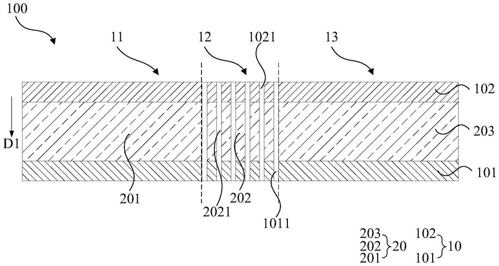
[0031] Such as figure 1 As shown, it is a schematic structural diagram of the support composite board 100 provided in the first embodiment of the present application; wherein, the support composite board 100 is applied to a foldable display panel, and the support composite board 100 includes a rigid support layer 10 and a heat dissipation layer 20; The rigid support layer 10 includes a first planar portion 11, a second planar portion 13 and a bent portion 12 between the first planar portion 11 and the second planar portion 13, and the heat dissipation layer 20 is embedded In the rigid support layer 10, the heat dissipation layer 20 includes a first heat dissipation portion 201 corresponding to the first planar portion 11, a second heat dissipation portion 203 corresponding to the second planar portion 13, and a The bridging portion 202 corresponding to the bent portion 12 , the first heat dissipation portion 201 and the second heat dissipation portion 203 are connected through...

Embodiment 2

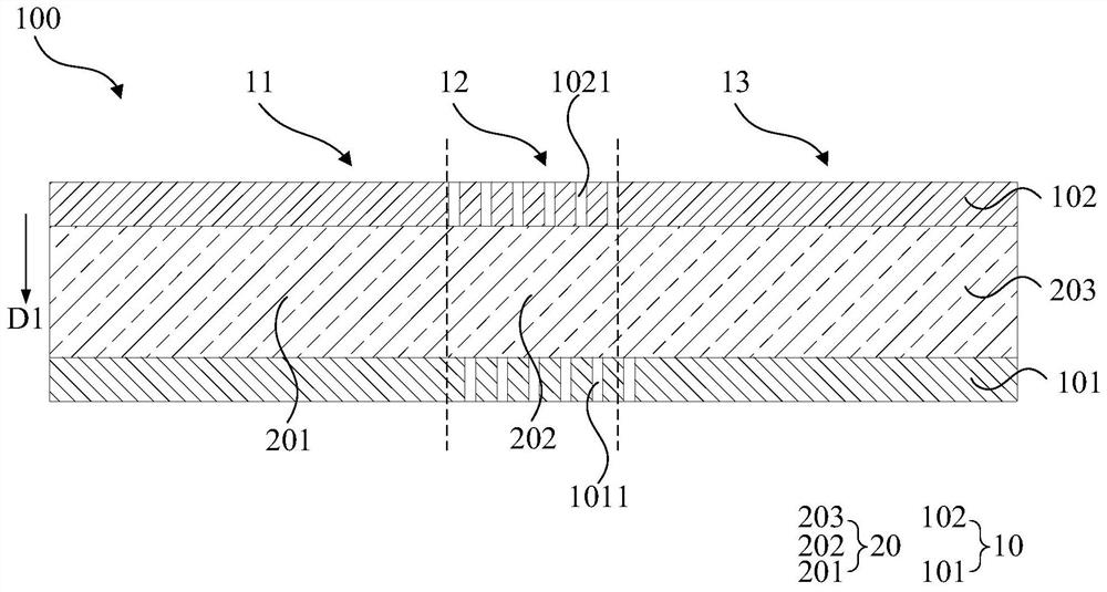
[0042] Such as figure 2 As shown, it is a schematic structural diagram of the supporting composite board 100 provided in the second embodiment of the present application; wherein, the structure of the supporting composite board 100 in the second embodiment of the present application is the same as that of the supporting composite board 100 in the first embodiment of the present application or Similar, the only difference is that the first opening 1011 runs through the first supporting layer 101 and exposes the surface of the heat dissipation layer 20 close to the first supporting layer 101, and the second opening 1021 runs through the The second support layer 102 exposes the surface of the heat dissipation layer 20 close to the second support layer 102; wherein, each of the first openings 1011 and each of the adjacent second openings 1021 are along the first opening 1021. One direction D1 is mutually misaligned.

[0043] In the second embodiment of the present application, o...


PUM


Abstract

The embodiment of the invention provides a supporting composite board and a display module. The supporting composite board is applied to the folding display panel, the supporting composite board comprises a rigid supporting layer and a heat dissipation layer, the rigid supporting layer comprises a first plane part, a second plane part and a bent part, the heat dissipation layer is embedded in the rigid supporting layer, the heat dissipation layer comprises a first heat dissipation part, a second heat dissipation part and a bridging part corresponding to the bent part, the first heat dissipation part and the second heat dissipation part are connected through a bridging part; according to the supporting composite board, the heat dissipation layer is embedded in the rigid supporting layer, the rigid supporting layer and the heat dissipation layer are integrally formed through the physical calendaring technology, on the premise that the folding function of the folding display panel is not affected, the supporting composite board provides the supporting function, and meanwhile the overall thickness of the supporting composite board is reduced, therefore, the purpose of reducing the weight of the supporting composite board is achieved.

Description

technical field [0001] The present application relates to the display field, in particular to a supporting composite board and a display module. Background technique [0002] With the development of science and technology, the appearance of mobile electronic devices has undergone tremendous changes. Flexible screens have attracted much attention due to their unique characteristics and huge potential, especially bendable smart devices. [0003] In the current DF (Dynamic Foldable, dynamically bendable) module screen, stainless steel material is usually used as the support layer of the display screen. The stainless steel material is mainly used to improve the stiffness of the screen in the non-bending area, so as to avoid serious appearance defects caused by bending and other processes. At the same time, due to the need for heat dissipation, a heat dissipation layer with higher thermal conductivity will be attached behind the stainless steel material to assist in heat dissipa...

Claims


Application Information

Patent Timeline
Patent Type & Authority Applications(China)
IPC IPC(8): G09F9/30H05K7/20
CPCG09F9/301H05K7/20963G06F1/203H10K59/8794H10K59/87H10K2102/311G06F2200/203H05K7/20509
Inventor 陈荣坤
Owner WUHAN CHINA STAR OPTOELECTRONICS SEMICON DISPLAY TECH CO LTD
Learn More