Deflection systemand and flat-shaped cathode-ray tube

A deflecting system, flat technology, applied in the direction of cathode ray tube indicator, cathode ray tube/electron beam tube, screen tube, etc., can solve the problem of lower productivity, higher cost of flat cathode ray tube, difficult winding of magnetic core, etc. problem, to achieve the effect of easy winding

Inactive Publication Date: 2004-02-11
SONY CORP
View PDF0 Cites 0 Cited by
  • Summary
  • Abstract
  • Description
  • Claims
  • Application Information

AI Technical Summary

Problems solved by technology

[0018] However, in the case of an elliptical core, the manufacture of the core and the winding of the coil become difficult due to its complex shape
[0019] As a resul

Method used


Image

  • Deflection systemand and flat-shaped cathode-ray tube
  • Deflection systemand and flat-shaped cathode-ray tube
  • Deflection systemand and flat-shaped cathode-ray tube

Examples


Embodiment Construction

[0032] Hereinafter, embodiments of the present invention will be described in detail with reference to the drawings.

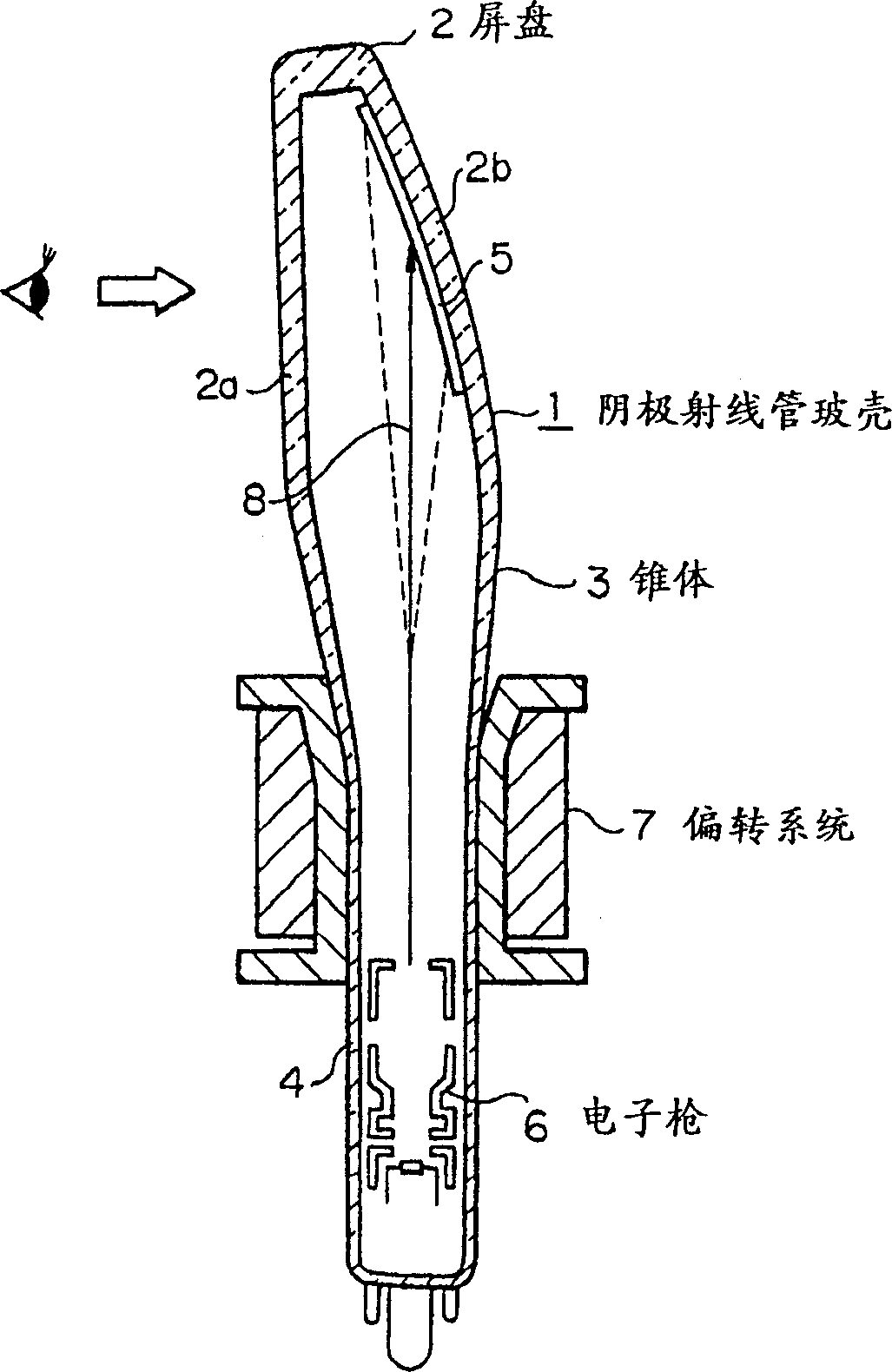
[0033] figure 1 It is a schematic side view showing the structure of the flat type cathode ray tube of the present invention.

[0034] exist figure 1 Among them, a cathode ray tube glass bulb (glass envelope) 1 is composed of a panel 2, a cone 3 and a tube neck 4.

[0035] The panel 2 has a front panel 2a and a rear panel 2b, and a fluorescent surface 5 is formed on the inner surface of the rear panel 2b.

[0036] On the other hand, an electron gun 6 is built in the neck 4 .

[0037] Furthermore, a deflection yoke 7 is mounted on the section from the neck 4 to the cone 3 .

[0038] In this flat type cathode ray tube, by deflecting electron beams 8 emitted from electron guns 6 by deflection yoke 7, an image is displayed on fluorescent surface 5 of rear panel 2b.

[0039] The display image (phosphor surface image) is observed from the direction indicated ...


PUM


Abstract

Provided is a deflection yoke capable of reducing a flat cathode-ray tube profile without increasing costs. This deflection yoke is provided with a pair of horizontal deflection coils 9 wound in a saddle shape as one end, a cylindrical core 13, and a pair of vertical deflecting coils 15 wound in a toroidal shape. The outer diameter of the core 13 is set approximately the same in the center axis Z-direction, the mounted position of the core 13 is set within a pair of horizontally deflected straight wound wires 12 and the pair of vertical deflection coils 15 is tightly disposed respective to the pair of horizontal deflection coils 9, thereby a maximum height Hv of the vertical deflection coils 15 is set smaller than Hh of the horizontal deflection coils 9.

Description

technical field [0001] The present invention relates to a flat type cathode ray tube (flat tube) mounted in a thin type developing device, and more particularly to a structure of a deflection yoke for a flat type cathode ray tube. Background technique [0002] Generally, since door intercoms with monitors and portable televisions require thin display devices, flat cathode ray tubes with small depths are incorporated in such display devices. [0003] In the flat type cathode ray tube, like a general cathode ray tube (for example, a cathode ray tube generally mounted in a picture tube in a home TV, a computer display device, etc.), equipped with a pair of horizontal deflection coils and a Deflection yoke for vertical deflection coils. [0004] Image 6 It is a diagram showing a coil structure of a deflection yoke used in a flat cathode ray tube, in which (a) is a perspective view showing a horizontal deflection coil structure, and (b) is a perspective view showing a vertical ...

Claims


Application Information

Patent Timeline
IPC IPC(8): H01J31/12G09G1/04H01J29/76H01J31/00
CPCH01J29/76H01J2229/581H01J2229/7031
Inventor 须藤一生山田敏房
Owner SONY CORP
Why Eureka
Try Eureka