Jaw osteotomy guide plate in-position indicating system

A guide plate and osteotomy technology, which is applied in the direction of bone drill guidance, medical science, surgery, etc., can solve the problem of inability to ensure that the inner surface and lower edge of the osteotomy guide plate fit closely with the bone surface, and the alignment is accurate. Lack of positioning indicating device, the fitting condition of the osteotomy guide plate cannot be determined, etc., to reduce bleeding and postoperative complications, improve accuracy and postoperative effect, and facilitate the promotion of use

Active Publication Date: 2021-12-24
WUHAN UNIV
View PDF15 Cites 0 Cited by
  • Summary
  • Abstract
  • Description
  • Claims
  • Application Information

AI Technical Summary

Problems solved by technology

[0004] However, the currently used clinical osteotomy guide plate lacks a positioning indicator device. When it is placed in the oral surgery area, due to the limitation of the size of the lips and the influence of local anatomy, only the fit between the upper edge of the guide plate and the bone surface can be seen in the field of vision.
However, the fit between the inner surface and the lower edge of the osteotomy guide plate and the bone surface cannot be determined, and it can only be determined by the operator's feeling and experience.
Therefore, it is impossible to ensure that the medial surface and lower edge of the osteotomy guide plate fit closely with the bone surface and the alignment is accurate during the operation.
When the lower part of the guide plate is tilted or rotated, it will lead to inaccurate osteotomy position, and even cause a series of problems such as intraoperative bleeding, accidental fracture, unsmooth osteotomy line, bilateral asymmetry, and unsatisfactory postoperative results.

Method used


Image

  • Jaw osteotomy guide plate in-position indicating system
  • Jaw osteotomy guide plate in-position indicating system
  • Jaw osteotomy guide plate in-position indicating system

Examples


Embodiment 1

[0028] 1. Preoperative data collection

[0029] After preoperative orthodontics, the patient's upper and lower jaw plaster models were taken for backup. The CT data of the patient's maxillofacial hard tissues were obtained through CT scanning. Use a three-dimensional scanner to scan the plaster models of the upper and lower jaws, and obtain the three-dimensional scanning files of the plaster models through corresponding software.

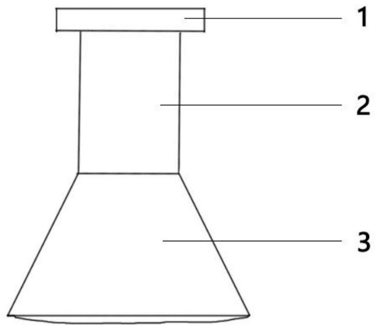
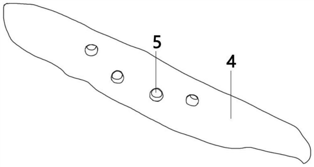
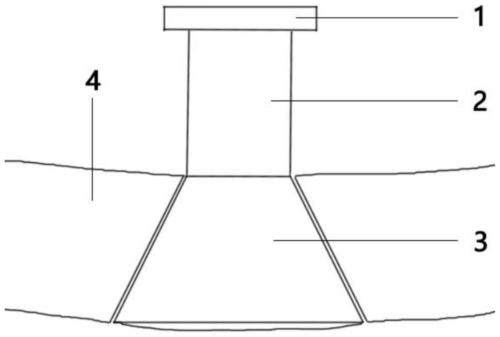
[0030] 2. Surgical design and manufacture of guide plate and guide plate in-position indicator device

[0031] Use digital 3D reconstruction software to obtain 3D reconstruction images of the patient's maxillofacial region, and import the 3D scan files of the plaster model to replace the dentition to obtain a clearer dentition and occlusion. According to the data of the patient's face shape, occlusion and cephalometric measurement, the surgical plan is designed, the osteotomy line is designed on the three-dimensional reconstruction image, and the ...


PUM


Abstract

The invention discloses a jaw osteotomy guide plate in-position indicating system which comprises an in-position indicating device, an osteotomy guide plate and an in-position hole. The in-position hole is formed in the osteotomy guide plate and matched with the in-position indicating device. The in-position indicating device comprises a thick column, a thin column and an outer side panel which serve as a main body, the in-position indicating device is integrally in a conical flask shape, the thick column and the thin column are directly and fixedly connected, the thin column is connected with the outer side panel, the in-position hole is integrally in a circular truncated cone shape, and the inner diameter of the hole channel is matched with the inner diameter of the thick column of the indicating device. Under the condition that the visual field is limited, whether the osteotomy guide plate is completely attached to the bone surface or not can be accurately judged, the position of the osteotomy line is visually and accurately determined, and the operation efficiency and accuracy are improved.

Description

technical field [0001] The invention belongs to the field of auxiliary medical devices, in particular to an in-position indicating system for a jaw osteotomy guide plate. Background technique [0002] Jaw bone is an important part of facial structure and function, but factors such as congenital malformation, trauma, tumor resection, and inflammatory reaction can lead to jaw bone deformity. Jaw deformity can be repaired by plastic surgery, among which jaw osteotomy is one of the most commonly used surgical methods to correct jaw deformity, such as maxillary Lefort type I osteotomy or mandibular sagittal split osteotomy for bone II , Class III dental and maxillofacial deformities, mandibular angle osteotomy for correction of mandibular angle hypertrophy, etc. The surgical approaches for jaw osteotomy mainly include extraoral, intraoral, and combined intraoral and extraoral approaches. The intraoral approach of jaw osteotomy is concealed, and there is no surgical trace left o...

Claims


Application Information

Patent Timeline
Patent Type & Authority Applications(China)
IPC IPC(8): A61B17/17
CPCA61B17/1732A61B17/176
Inventor 万启龙吴姝萱刘念柯周奕娆党俊杰马至功
Owner WUHAN UNIV
Why Eureka
Try Eureka