Perforating device special for electric power installation parts

A technology for punching devices and mounting parts, which is applied in the directions of positioning devices, feeding devices, maintenance and safety accessories, etc. It can solve the problems of increased labor intensity, large use limitations, and cumbersome use, and achieves wide application range, easy to move, The effect of clamping stability

Pending Publication Date: 2021-12-24
国网河南省电力公司禹州市供电公司
View PDF0 Cites 0 Cited by
  • Summary
  • Abstract
  • Description
  • Claims
  • Application Information

AI Technical Summary

Problems solved by technology

[0002] Because electric energy is easy to convert, transmit, and control, it has gradually replaced steam power and has become the technical foundation of material and spiritual civilization in modern society. Electric power engineering, that is, engineering related to the production, transmission, and distribution of electric energy, also includes electricity as Power and energy are applied in various fields. During the construction of electric power engineering, a large number of supporting installation equipment needs to be laid. Such equipment can be called power installation parts. During the use of power installation parts, power The installation part is punched, and it needs to be positioned to ensure the accuracy of the drilling position. According to the shape, most of the power installation parts are plate-shaped or tubular. At present, the punching equipment can only be used for one shape. The power installation parts are clamped and fixed, the use is limited, and the position of the drilling bit is fixed, and the power installation parts can only be moved frequently during continuous drilling, which is cumbersome to use, and the material residue generated during drilling needs special cleaning, which is time-consuming and laborious. , increase labor intensity

Method used


Image

  • Perforating device special for electric power installation parts
  • Perforating device special for electric power installation parts
  • Perforating device special for electric power installation parts

Examples


Embodiment 1

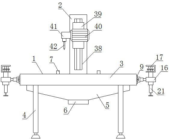
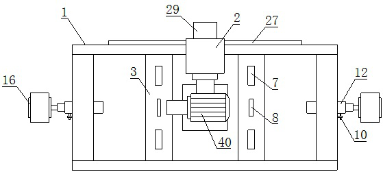
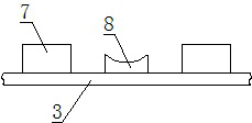
[0029] Such as Figure 1-11 As shown, a special punching device for power installation parts, which includes a placing table 1 and a lifting seat 2, a foot 4 is provided under the placing table 1, and a platen 3 is provided on the upper side of the placing table 1. A support plate 7 is provided on the upper side of the table 3, a support ring 8 is provided on the inner side of the support plate 7, bearing seats 9 are provided on the left and right sides of the placement platform 1, and the front side of the bearing seat 9 is A fixed plate 10 is provided, the inside of the fixed plate 10 is provided with a positioning bolt 11, the middle part of the bearing seat 9 is provided with a rod tube 12, the inside of the rod tube 12 is provided with a telescopic rod 14, and the described telescopic rod 14 is provided with a clip bar 15, the end of the telescopic rod 14 is provided with a support plate 16, and a plate clamp seat 17 is provided above the support plate 16, and a spring 18...

Embodiment 2

[0038] Such as Figure 1-11 As shown, a special punching device for power installation parts, which includes a placing table 1 and a lifting seat 2, a foot 4 is provided under the placing table 1, and a platen 3 is provided on the upper side of the placing table 1. A support plate 7 is provided on the upper side of the table 3, a support ring 8 is provided on the inner side of the support plate 7, bearing seats 9 are provided on the left and right sides of the placement platform 1, and the front side of the bearing seat 9 is A fixed plate 10 is provided, the inside of the fixed plate 10 is provided with a positioning bolt 11, the middle part of the bearing seat 9 is provided with a rod tube 12, the inside of the rod tube 12 is provided with a telescopic rod 14, and the described telescopic rod 14 is provided with a clip bar 15, the end of the telescopic rod 14 is provided with a support plate 16, and a plate clamp seat 17 is provided above the support plate 16, and a spring 18...


PUM


Abstract

The invention relates to a perforating device special for electric power installation parts. The perforating device comprises a containing table and a lifting seat, a supporting plate and a supporting ring are arranged at the upper side of a table plate and can respectively support the plate-shaped installation part and the tubular installation part, a rod barrel can be fixed by a positioning bolt through a positioning hole, and a plate clamping seat and a tube clamping seat are respectively arranged at the upper side and the lower side of a supporting disc; the plate clamping seat can fix the plate-shaped installation part through a pressing plate, the pipe clamping seat can fix the tubular installation part through a clamping plate, a lifting seat is connected with the containing table through a sliding groove, the lifting seat can move left and right along a sliding plate, continuous perforating is facilitated, a lifting motor is started to drive a threaded column to rotate, the threaded column can drive a lifting plate to move up and down, a drilling motor is fixedly connected with the lifting plate, and the drilling motor is started to drive a drill bit to rotate for drilling operation. The perforating device has the characteristics of being stable in clamping, convenient to move, wide in application range and good in punching effect.

Description

technical field [0001] The invention belongs to the technical field of electric power construction, and in particular relates to a special punching device for electric power installation parts. Background technique [0002] Because electric energy is easy to convert, transmit, and control, it has gradually replaced steam power and has become the technical foundation of material and spiritual civilization in modern society. Electric power engineering, that is, engineering related to the production, transmission, and distribution of electric energy, also includes electricity as Power and energy are applied in various fields. During the construction of electric power engineering, a large number of supporting installation equipment needs to be laid. Such equipment can be called power installation parts. During the use of power installation parts, power The installation part is punched, and it needs to be positioned to ensure the accuracy of the drilling position. According to th...

Claims


Application Information

Patent Timeline
Patent Type & Authority Applications(China)
IPC IPC(8): B23B39/00B23B47/20B23Q3/06B23Q1/25B23Q11/00
CPCB23B39/00B23Q3/06B23Q5/40B23Q1/25B23Q11/0067
Inventor 李军伟张彦博钦仿仿
Owner 国网河南省电力公司禹州市供电公司
Why Eureka
Try Eureka