Unmanned car washing device for smart city
An urban and smart technology, applied in vehicle drying devices, vehicle exterior cleaning devices, vehicle maintenance, etc., can solve the problems of discounted cleaning effect, high equipment manufacturing cost, difficult to clean vehicle wheels, etc., to improve cleaning effect, reduce costs, The effect of reducing dead angle
- Summary
- Abstract
- Description
- Claims
- Application Information
AI Technical Summary
Problems solved by technology
Method used
Image

Examples
Embodiment 2
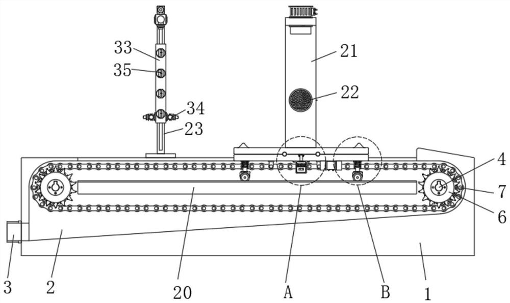
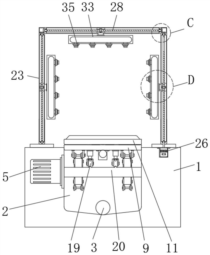
[0031] Limiting blocks 12 are arranged on the opposite right sides of the upper end of the receiving seat 11, and the longitudinal section of the limiting block 12 can be a triangle, or a circular arc-shaped convex structure, or a polygonal convex structure, which can facilitate the vehicle Drive into the realization limit, such as figure 1 and figure 2 , the limit block 12 is used to limit the front and rear wheels of the vehicle to prevent the vehicle from slipping and falling from the receiving seat 11, and infrared rays are respectively arranged at the corresponding positions of the middle of the limit block 12 and the bottom of the second fixing frame 23 Emitter and infrared receiver, control wheel cleaning nozzle 34 work when infrared receiver receives infrared signal, can guarantee wheel cleaning nozzle 34 to face vehicle this moment, wheel is positioned at the extension line of wheel cleaning nozzle 34 inclination angles.
[0032] On the basis of the above technical ...
PUM
 Abstract
Description
Claims
Application Information
 - R&D
- Intellectual Property
- Life Sciences
- Materials
- Tech Scout
- Unparalleled Data Quality
- Higher Quality Content
- 60% Fewer Hallucinations
Browse by: Latest US Patents, China's latest patents, Technical Efficacy Thesaurus, Application Domain, Technology Topic, Popular Technical Reports.
© 2025 PatSnap. All rights reserved.Legal|Privacy policy|Modern Slavery Act Transparency Statement|Sitemap|About US| Contact US: help@patsnap.com