A wire-guided automatic pay-off device and method

A technology of pay-off device and guide device, which is applied in drilling equipment and methods, directional drilling, earthwork drilling and mining, etc., which can solve problems such as high labor cost, low pay-out efficiency, and chaotic winding of guide wires, and achieve labor cost savings , Improve the effect of construction efficiency

Active Publication Date: 2022-02-22
XUZHOU XUGONG FOUND CONSTR MACHINERY
View PDF8 Cites 0 Cited by
  • Summary
  • Abstract
  • Description
  • Claims
  • Application Information

AI Technical Summary

Problems solved by technology

In the construction process of wired guidance, the guide line needs to be inserted into the center hole of the drill pipe. After the power head completes a propulsion process, it needs to return to add a new drill pipe to start the next propulsion process. Each additional drill pipe needs to be rewired. Now it is generally It is a drill pipe that manually draws the measured length line on the construction equipment and penetrates one end of the drill pipe into the center hole of the drill pipe. It is easy to cause confusion in the winding of the guide line. Both ends of the drill pipe need to be operated by someone, and the drill pipe is driven into the soil. The line in the center hole cannot be automatically in a tensioned state. Because there will be backflow mud in the center hole, it is easy to be stirred by the impact of the mud, causing the guide line to break at the joint and lead to the failure of the guide process. It is necessary to drag the drill pipe back from the beginning. , so the construction risk is high, the labor cost is high, and the line efficiency is low

Method used


Image

  • A wire-guided automatic pay-off device and method
  • A wire-guided automatic pay-off device and method
  • A wire-guided automatic pay-off device and method

Examples


Embodiment Construction

[0027] The present invention will be described in further detail below in conjunction with the accompanying drawings and specific embodiments.

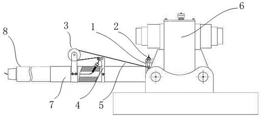
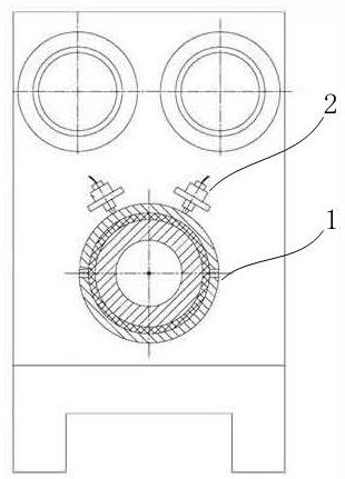
[0028] Such as figure 1 As shown, a wire-guided automatic pay-off device is installed on a horizontal directional drilling machine. The horizontal directional drilling machine includes a power head assembly 6, a short joint 7 and a drill pipe 8, and the rear end of the short joint 7 is connected to the main shaft of the power head assembly 6. It is fixedly connected and rotates with the main shaft, and the front end is connected with the drill rod 8. The pay-off device includes a conductive ring assembly 1, a brush assembly 2, a winding device 3, a guide device 4 and a guide wire 5. The conductive ring assembly 1 is fixed on the main shaft of the power head assembly 6 and rotates together with the main shaft. The brush assembly 2 is fixed on the body of the power head assembly 6 and does not rotate with the main shaft. The conductive...


PUM


Abstract

The invention discloses a wire-guided automatic pay-off device and method. The device is installed on a horizontal directional drilling machine. The pay-off device includes a conductive ring assembly, a brush assembly, a winding device, a guide device and a guide wire. The assembly is fixed on the main shaft of the power head assembly and rotates with the main shaft. The brush assembly is fixed on the body of the power head assembly and does not rotate with the main shaft. The conductive end of the brush assembly is in contact with the conductive ring assembly. The guide wire is wound on the winding device, one end of which is connected to the conductive ring assembly, the other end passes through the guide device, and penetrates into the central hole in the drill pipe from the rear end, and then emerges from the front end of the drill pipe and is pushed into the The guide wires in the drill pipes of the working face are connected to form a complete tight guide wire. The device can keep the guide wire in a tight state, prevent it from being disconnected at the joint of the guide wire, and can realize automatic pay-off and improve pay-off efficiency.

Description

technical field [0001] The invention relates to the technical field of horizontal directional drilling rigs, in particular to a wired-guided automatic pay-off device and method. Background technique [0002] The construction process of the trenchless horizontal directional drilling rig includes three processes: pilot hole drilling, hole reaming and pipe pullback. Among them, the process of drilling pilot holes is a key link, which is directly related to whether the pipeline can be laid according to the prescribed track. Therefore, the key technology of trenchless pipe laying lies in the precise control of the directional drilling trajectory to ensure that the original underground pipelines and obstacles are avoided, and the pipe is laid accurately and smoothly according to the designed route. The control of the trajectory of the pilot hole depends on the signal emitted by the probe in the pilot drill bit, which is transmitted to the display of the console through the signal...

Claims


Application Information

Patent Timeline
Patent Type & Authority Patents(China)
IPC IPC(8): B65H49/18B65H57/14B65H59/06E21B7/04
CPCB65H49/18B65H57/14B65H59/06E21B7/046B65H2701/34
Inventor 闫志霞孔庆华李根营李明杨明张力王祥石硕
Owner XUZHOU XUGONG FOUND CONSTR MACHINERY
Why Eureka
Try Eureka