Miniature beam-expanding optical fiber contact element

A beam-expanding optical fiber and contact piece technology, applied in the field of miniature beam-expanding optical fiber contact pieces, can solve the problems of the optical fiber connector not working normally, increasing the insertion loss of the connector, and unable to realize signal transmission, etc., so as to improve the anti-pollution ability, The effect of reducing sensitivity and improving coupling efficiency

Pending Publication Date: 2021-12-24
沈阳兴华航空电器有限责任公司
View PDF0 Cites 0 Cited by
  • Summary
  • Abstract
  • Description
  • Claims
  • Application Information

AI Technical Summary

Problems solved by technology

If there are dust particles on the end face of the optical fiber, the optical signal will be blocked, and even the end face of the optical fiber will be damaged, which will eventually lead to the failure of the optical fiber connector to work normally.
Since the optical fiber of the physical contact connector is in contact with the end face of the optical fiber, when subjected to vibration, the end face of the optical fiber is constantly rubbed, which will cause damage to the end face of the optical fiber and increase the insertion loss of the connector, so it cannot be applied to fields with frequent vibrations
If the connector is docked repeatedly for too many times, the end face of the fiber will be damaged, and the loss of the connector will increase until the signal transmission cannot be realized, so the mechanical life of the physical contact fiber optic connector is short

Method used


Image

  • Miniature beam-expanding optical fiber contact element
  • Miniature beam-expanding optical fiber contact element
  • Miniature beam-expanding optical fiber contact element

Examples


Embodiment Construction

[0020] In order to make the technical problems, technical solutions and beneficial effects solved by the present invention clearer, the present invention will be further described in detail below in conjunction with the accompanying drawings and specific implementation methods. It should be understood that the specific embodiments described here are only used to explain the present invention, and are not intended to limit the present invention.

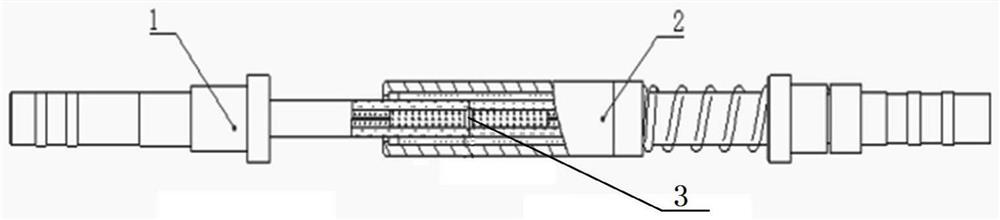
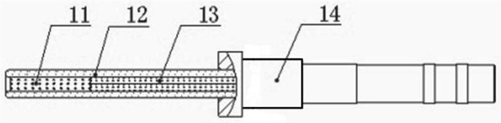
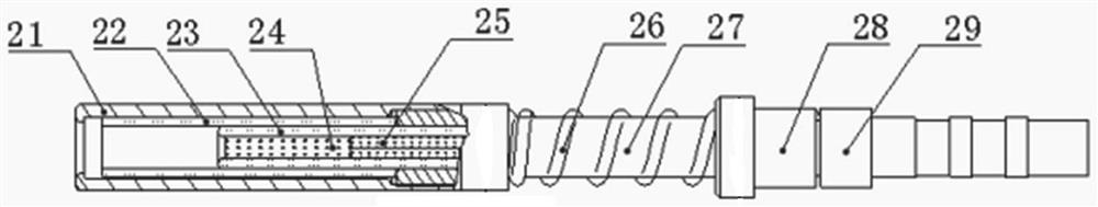
[0021] Such as Figure 1 to Figure 3 As shown, a micro-expanded optical fiber contact of the present invention includes a pin 1 and a socket 2, and the pin 1 is connected to the socket 2; the pin 1 includes a self-focusing lens 11 at the pin end, a closed pin at the pin end A ceramic sleeve 12, a needle end ferrule 13 and a needle end housing 14, the needle end housing 14 is connected to the needle end closed ceramic sleeve 12, and the needle end closed ceramic sleeve 12 is provided with a needle end ferrule 13 . The needle-end self-...


PUM

PropertyMeasurementUnit
sizeaaaaaaaaaa

Abstract

The invention discloses a miniature beam-expanding optical fiber contact element. A pin comprises a pin end self-focusing lens, a pin end closed ceramic sleeve, a pin end insertion core and a pin end shell. The pin end shell is connected with the pin end closed ceramic sleeve, the pin end insertion core and the pin end self-focusing lens are arranged in the pin end closed ceramic sleeve. The pin end self-focusing lens is arranged at a pipe opening close to the pin end closed ceramic sleeve; the jack comprises a jack end self-focusing lens, a jack end closed ceramic sleeve, a jack end insertion core and a jack end shell. The jack end shell is connected with the jack end closed ceramic sleeve, the jack end insertion core and the jack end self-focusing lens are arranged in the jack end closed ceramic sleeve, and the jack end self-focusing lens is arranged at the position close to a pipe opening of the jack end closed ceramic sleeve; the pin end closed ceramic bushing of the pin is in butt joint with the hole end closed ceramic bushing of the jack. The self-focusing lens is adopted to collimate the optical fiber light spots, non-contact optical signal transmission is achieved, the anti-pollution capacity of the optical fiber contact piece is improved, and the mechanical life of the optical fiber contact piece is prolonged.

Description

technical field [0001] The invention belongs to the technical field of optical fiber connectors, and in particular relates to a miniature beam expanding optical fiber contact piece. Background technique [0002] The light transmission type of fiber optic connector can be divided into two categories: physical contact type and non-physical contact beam expansion type. Physical contact type is the main connection mode at present, and signal transmission is realized through the close connection of optical fiber end faces. , The cost of physical contact connectors is lower, but there are still problems in terms of field cleanability and sensitivity to dust. If there are dust particles on the end face of the optical fiber, the optical signal will be blocked, and even the end face of the optical fiber will be damaged, which will eventually cause the optical fiber connector to fail to work normally. Since the optical fiber of the physical contact connector is in contact with the en...

Claims


Application Information

Patent Timeline
Patent Type & Authority Applications(China)
IPC IPC(8): G02B6/38
CPCG02B6/3807G02B6/3833G02B6/3853
Inventor 高阳李凯冯浩王可冯柏润孙海航王樱霖
Owner 沈阳兴华航空电器有限责任公司
Why Eureka
Try Eureka