Non-line-of-sight image reconstruction method, device and system and computer readable storage medium
An image reconstruction, non-line-of-sight technology, applied in the field of non-line-of-sight imaging, can solve the problems of time-consuming and non-line-of-sight imaging difficulties, and achieve the effect of fast parallel non-line-of-sight imaging
- Summary
- Abstract
- Description
- Claims
- Application Information
AI Technical Summary
Problems solved by technology
Method used
Image
Examples
Embodiment 1
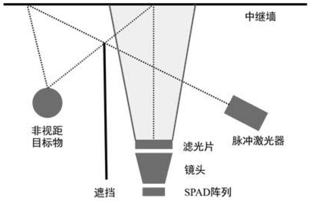
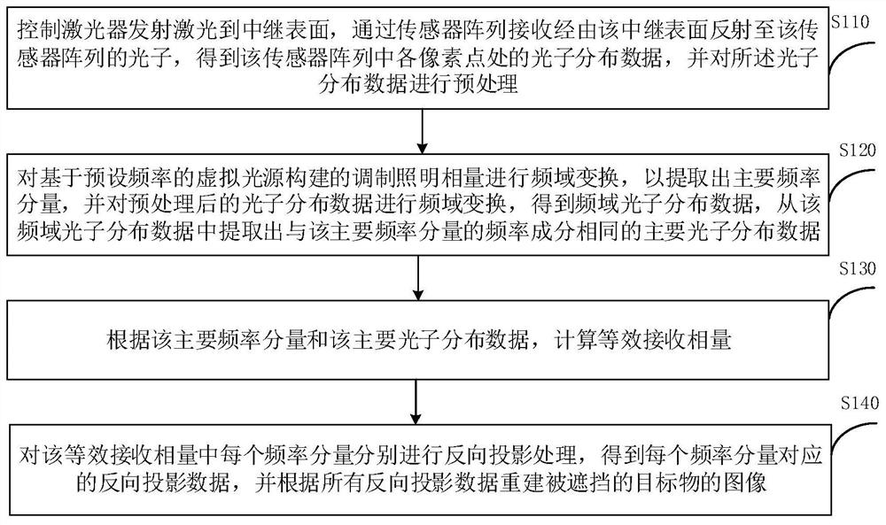
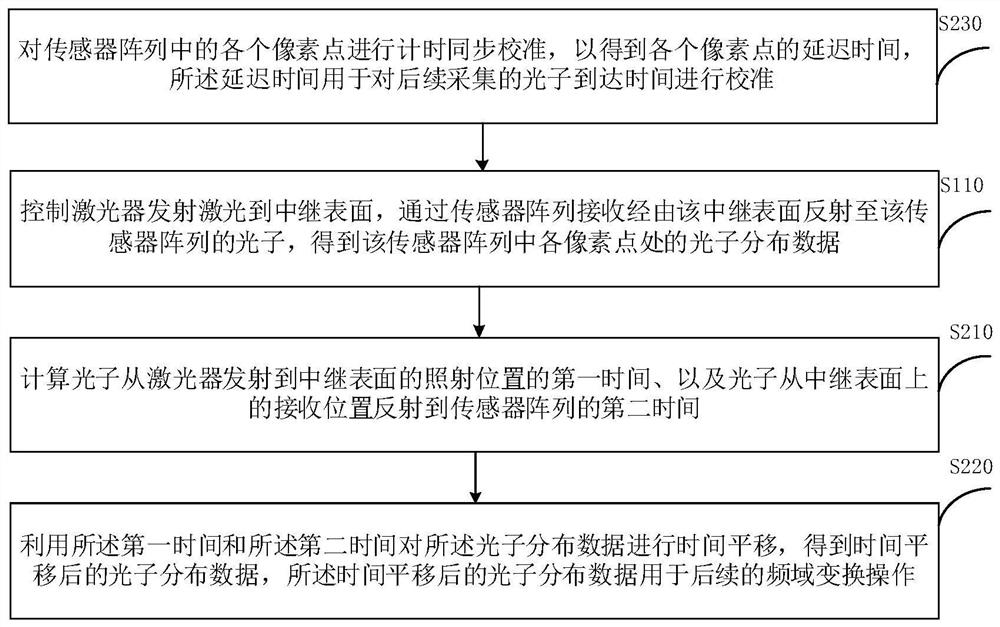
[0058] Please refer to figure 1 and 2 , this embodiment proposes a non-line-of-sight image reconstruction method, which can be applied to scenes that require non-line-of-sight imaging, such as industrial monitoring, vehicle navigation, and collision avoidance.
[0059] Such as figure 1 As shown, in a non-line-of-sight imaging scene, there are usually non-line-of-sight targets, relays (here, a relay wall is taken as an example) and occluders. Since the target is occluded, it is impossible to directly obtain the Therefore, the non-line-of-sight image reconstruction method of this embodiment will use lasers, optical sensor array components, etc. to obtain the image of the occluded target object. In addition, the data collected by the optical sensor array will be synchronized to the computer and other terminal equipment , to perform data analysis and finally obtain the reconstructed image of the target object.
[0060] Among them, the laser is mainly used to emit high-frequency...
Embodiment 2
[0111] Please refer to Figure 7 , based on the method of the above-mentioned embodiment 1, this embodiment also proposes a non-line-of-sight image reconstruction method. The difference from the above-mentioned embodiment 1 is that the above-mentioned embodiment is mainly based on the modulated illumination phasor of a virtual light source with a set frequency. reconstruction, and this embodiment performs reconstruction by combining at least two modulated illumination phasors, so as to optimize the reconstructed image quality during non-line-of-sight imaging.
[0112] Exemplarily, the non-line-of-sight image reconstruction method includes:
[0113] Step S310, controlling the laser to emit laser light to the relay surface, receiving photons reflected by the relay surface to the sensor array through the sensor array, obtaining photon distribution data at each pixel point in the sensor array, and pre-processing the photon distribution data deal with.
[0114] Wherein, step S310...
Embodiment 3
[0127] Please refer to Figure 8 , based on the method of Embodiment 1 or 2 above, this embodiment also proposes a non-line-of-sight image reconstruction device 100. Exemplarily, the non-line-of-sight image reconstruction device 100 includes:
[0128] The acquisition module 110 is configured to control the laser to emit laser light to the relay surface, receive photons reflected by the relay surface to the sensor array through the sensor array, obtain photon distribution data at each pixel point in the sensor array, and Preprocessing is performed on the photon distribution data.
[0129] The extraction module 120 is configured to perform frequency-domain transformation on the modulated lighting phasor constructed based on a virtual light source with a preset frequency to extract main frequency components, and perform frequency-domain transformation on the preprocessed photon distribution data to obtain frequency-domain photon distribution data, extracting main photon distribu...
PUM
 Abstract
Description
Claims
Application Information
 - R&D
- Intellectual Property
- Life Sciences
- Materials
- Tech Scout
- Unparalleled Data Quality
- Higher Quality Content
- 60% Fewer Hallucinations
Browse by: Latest US Patents, China's latest patents, Technical Efficacy Thesaurus, Application Domain, Technology Topic, Popular Technical Reports.
© 2025 PatSnap. All rights reserved.Legal|Privacy policy|Modern Slavery Act Transparency Statement|Sitemap|About US| Contact US: help@patsnap.com


