Scintillation screen coupling method
A technology of scintillation screen and coupling surface, applied in the field of scintillation screen coupling, can solve the problem of the scintillation screen being crushed, and achieve the effect of small curing shrinkage, reducing position change or tilt, and improving yield rate.
- Summary
- Abstract
- Description
- Claims
- Application Information
AI Technical Summary
Problems solved by technology
Method used
Image

Examples
Embodiment 1
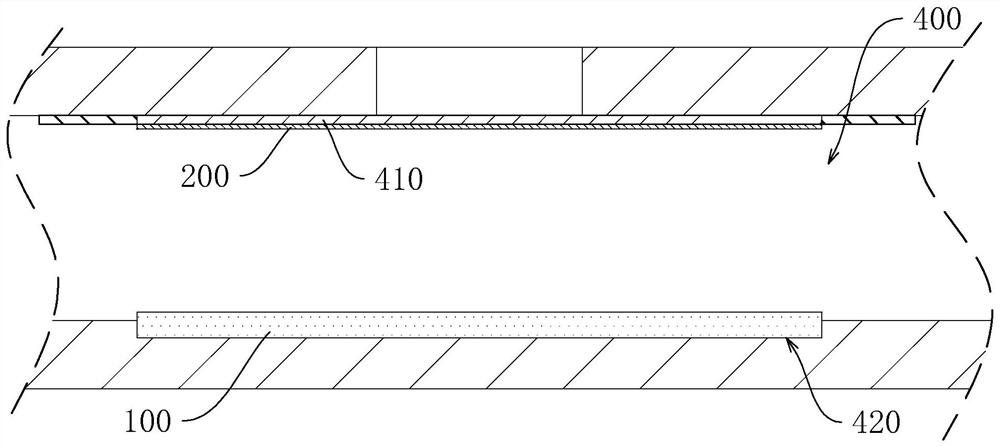
[0060] refer to figure 1 , a scintillation screen coupling method mainly includes the following steps:
[0061] S1:
[0062] S1.1: Clean the surface of the scintillation plate 100 to reduce the rate of defective products caused by the existence of impurities. The scintillation plate 100 is then placed in a vacuum chamber 400 . The vacuum chamber 400 is provided with a bottom groove 420 for fixing the position of the scintillation plate 100 , and the scintillation plate 100 can just be snapped into the bottom groove 420 .
[0063] S1.2: Paste the optical adhesive 200 on the center of the elastic seal 410 of the vacuum chamber 400 . The optical adhesive 200 is OCA optical adhesive with release paper on at least one side. It is worth noting that: the side of the optical adhesive 200 with the release paper faces the elastic sealing member 410 , and the OCA optical adhesive and the elastic sealing member 410 are separated by the release paper. For the convenience of operation,...
Embodiment 2
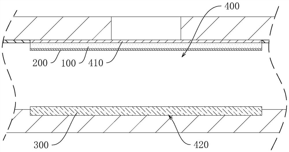
[0082] refer to figure 2 , a scintillation screen coupling method, the difference between this embodiment and embodiment 1 is:
[0083] S4:
[0084] S41 : place the sensor 300 in the bottom groove 420 of the vacuum chamber 400 , make its coupling face up and align with the center of the elastic seal 410 .
[0085] S42: Bond the scintillation plate 100 adhered with the optical glue 200 to the center of the elastic sealing member 410, and the side of the scintillating plate 100 bonded with the optical glue 200 faces away from the elastic sealing member 410. Tear off the release paper of Optical Adhesive 200.
[0086] The implementation sequence of the two steps of S41 and S42 can be exchanged or performed simultaneously. In this embodiment, S41 is performed first, and then S42 is performed.
[0087] S5:
[0088] Start the vacuum pump, and use the vacuum pump to evacuate the inside of the vacuum chamber 400 . Under the action of atmospheric pressure, the elastic sealing me...
Embodiment 3
[0098] see Figure 4 and Figure 5 , a scintillation screen coupling method, the difference between this embodiment and embodiment 2 is:
[0099] see Figure 4 , in S10, the coupling surface of the sensor 300 is cleaned, so as to reduce the increase of the defective product rate caused by the existence of impurities. Then the sensor 300 is placed in the bottom groove 420 of the vacuum chamber 400 . The coupling surface of the sensor 300 is aligned with the center of the elastic seal 410 .
[0100] see Figure 4 , in S2, use a vacuum pump to evacuate the inside of the vacuum chamber 400 to reduce the air pressure in the vacuum chamber 400 . The elastic seal 410 approaches the sensor 300 under the action of atmospheric pressure, bonding and pressing the optical adhesive 200 to the sensor 300 .
[0101] see Figure 5 , in S4:
[0102] S41: Remove the release paper on the side of the optical adhesive 200 away from the sensor 300 .
[0103] S42 : cleaning the scintillation...
PUM
 Abstract
Description
Claims
Application Information
 - R&D
- Intellectual Property
- Life Sciences
- Materials
- Tech Scout
- Unparalleled Data Quality
- Higher Quality Content
- 60% Fewer Hallucinations
Browse by: Latest US Patents, China's latest patents, Technical Efficacy Thesaurus, Application Domain, Technology Topic, Popular Technical Reports.
© 2025 PatSnap. All rights reserved.Legal|Privacy policy|Modern Slavery Act Transparency Statement|Sitemap|About US| Contact US: help@patsnap.com