
Chemical cleaning system and method for high-temperature and high-pressure experimental facility

A high-temperature, high-pressure, chemical cleaning technology, applied to chemical instruments and methods, cleaning methods using liquids, cleaning methods and utensils, etc., can solve problems such as high vacuum requirements and affecting experimental water quality, so as to reduce energy consumption and achieve good results. Clearing effect, effect of reducing heat exchange power

Active Publication Date: 2021-12-28
XIAN THERMAL POWER RES INST CO LTD
View PDF7 Cites 0 Cited by
  • Summary
  • Abstract
  • Description
  • Claims
  • Application Information

AI Technical Summary

Problems solved by technology

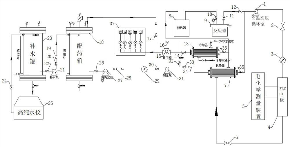
[0004] Compared with the chemical cleaning of conventional experimental equipment, the chemical cleaning of high-temperature and high-pressure experimental equipment has the following difficulties: 1) The high-temperature and high-pressure experimental equipment works at a high temperature of 300 ° C. Usually, the residue after cleaning with cleaning agents may decompose under high temperature conditions. If the water quality of the experiment is affected, the experimental device must be chemically cleaned with less residual lotion at 300°C; 2) After the high-temperature and high-pressure experimental device is cleaned at 300°C, the pressure of the cleaning cycle is also very high, and the working pressure is About 10MPa, conventional high-pressure pumps have high requirements for suction vacuum, so this cleaning system adopts a two-stage pump in series for dosing, and the cleaning and dosing pump provides output to ensure that the suction vacuum of the high-pressure pump meets the rated parameter requirements; 3) Since the on-line measurement device and manual sampling need to work at normal temperature and pressure, the high-temperature cleaning fluid in the cleaning cycle of the high-temperature and high-pressure device will vaporize after entering the normal pressure, and the follow-up device cannot work normally and must be cooled

Method used


Image

  • Chemical cleaning system and method for high-temperature and high-pressure experimental facility

Examples


Embodiment Construction

[0031] In order to enable those skilled in the art to better understand the technical solutions in the present invention, the technical solutions in the embodiments of the present invention will be clearly and completely described below in conjunction with the drawings in the embodiments of the present invention. Obviously, the described The embodiments are only some of the embodiments of the present invention, not all of them. Based on the embodiments of the present invention, all other embodiments obtained by persons of ordinary skill in the art without making creative efforts shall fall within the protection scope of the present invention.

[0032] It should be noted that when an element is referred to as being “disposed on” another element, it may be directly on the other element or there may also be an intervening element. When an element is referred to as being "connected to" another element, it can be directly connected to the other element or intervening elements may a...


PUM


Abstract

The invention relates to a chemical cleaning system and method for a high-temperature and high-pressure experimental facility. The cleaning system comprises a high-purity water instrument and a dosing box, the dosing box is connected to a heat exchanger through a cleaning dosing pump and a dosing pipeline, then cleaning fluid enters the high-temperature and high-pressure experimental facility, and cleaning power is provided by a high-temperature and high-pressure circulating pump; After passing through an outlet door of the circulating pump, the cleaning fluid enters a flow accelerated corrosion measuring electrode and then enters the heat exchanger to exchange heat, and after heat exchange, one path passes through a preheater and a reaction kettle to continue circular cleaning in an experimental loop; and the other path is cooled by a cooler, the pressure of the experimental circulation loop is maintained by a back pressure valve, and then the cleaning fluid returns to the dosing box for continuous circulation. By means of the system and method, systematic and efficient cleaning of the high-temperature and high-pressure experimental facility can be achieved, various kinds of grease such as various corrosion products, anti-rust oil, cutting lubricating oil and sealing oil can be completely removed, it is guaranteed that the interior of the high-temperature and high-pressure experimental facility is clean, and the accuracy of experimental results is guaranteed.

Description

technical field [0001] The invention belongs to the technical field of chemical cleaning of high-temperature and high-pressure experimental devices, and in particular relates to a chemical cleaning system and method for high-temperature and high-pressure experimental devices. Background technique [0002] The high-temperature and high-pressure experimental device is the key equipment for studying the evaluation of metal corrosion status under high-temperature conditions in the water vapor system. However, due to the high operating temperature, the cleanliness of the entire system is very high. If it cannot be cleaned, the water quality of the experimental system will be affected after the experiment is started. , causing unnecessary corrosion, thereby affecting the experimental results. A large number of corrosion products may enter key experimental equipment such as autoclaves with the water vapor cycle of the experimental device, causing further corrosion and even affectin...

Claims


Application Information

Patent Timeline
IPC IPC(8): B08B3/02B08B3/10B08B13/00
CPCB08B3/02B08B3/10B08B13/00Y02E30/30
Inventor 姚建涛张贵泉龙国军刘薇陈甜甜
Owner XIAN THERMAL POWER RES INST CO LTD
Learn More