
Projection equipment and shell thereof

A technology for projection equipment and shells, applied in optics, instruments, projection devices, etc., can solve problems such as thermal defocusing

Active Publication Date: 2021-12-28
SHENZHEN HUOLE TECH DEV CO LTD
View PDF5 Cites 0 Cited by
  • Summary
  • Abstract
  • Description
  • Claims
  • Application Information

AI Technical Summary

Problems solved by technology

[0003] The embodiment of the present disclosure provides a projection device and its housing, which can solve the technical problem that the projection device in the prior art is prone to thermal out-of-focus during operation

Method used


Image

  • Projection equipment and shell thereof
  • Projection equipment and shell thereof
  • Projection equipment and shell thereof

Examples


Embodiment Construction

[0040] The following will clearly and completely describe the technical solutions in the embodiments of the present disclosure with reference to the accompanying drawings in the embodiments of the present disclosure. Apparently, the described embodiments are only some of the embodiments of the present disclosure, not all of them. Based on the embodiments in the present disclosure, all other embodiments obtained by those skilled in the art without creative efforts fall within the protection scope of the present disclosure. In addition, it should be understood that the specific embodiments described here are only used to illustrate and explain the present disclosure, and are not intended to limit the present disclosure. In the present disclosure, unless stated otherwise, the used orientation words such as "up" and "down" generally refer to up and down in the actual use or working state of the device, specifically the direction of the drawings in the drawings ; while "inside" and...


PUM


Abstract

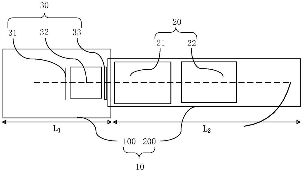
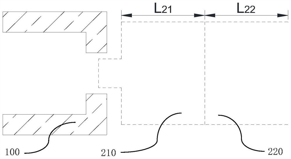
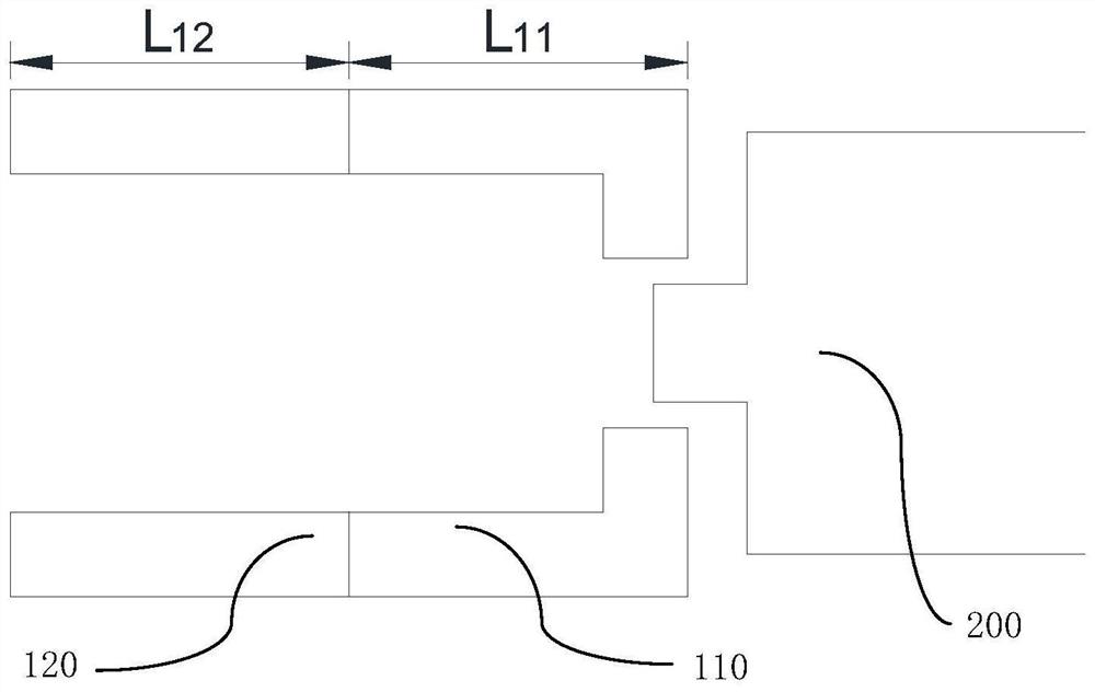
The embodiment of the invention discloses projection equipment and a shell thereof. The projection equipment shell comprises a light machine shell and a lens shell, and the light machine shell and the lens shell are arranged in the direction of an optical axis and are connected with each other; and the thermal expansion coefficient of the light machine shell is smaller than that of the lens shell. The light machine shell with the small thermal expansion coefficient and the lens shell with the large thermal expansion coefficient are selected to be combined, so that thermal defocusing caused by different expansion deformation degrees of the light machine shell and the lens shell is improved. In the using process, the working temperature of the light machine is higher, and the deformation degree of the light machine is larger, so that the thermal expansion coefficient of the lens shell is increased while the thermal expansion coefficient of the light machine shell is inhibited, the deformation of the light machine shell and the deformation of the lens shell are kept consistent, the change degree of the focal length is reduced, so that the technical problem that in the prior art, the projection equipment is prone to thermal defocusing during working is solved.

Description

technical field [0001] The present disclosure relates to the field of display, in particular to a projection device and its casing. Background technique [0002] The ultra-short-throw projector is one of the mainstream projection solutions for smart projection and laser TV products. Its main advantage is that it can project a large enough picture at a short distance. Compared with other mid-telephoto projectors, this This projection method can significantly save projection space, and the projector can be placed directly close to the curtain or wall; however, due to the imaging principle of ultra-short-throw projection, the depth of field of the imaging picture is shallow, and a slight focal length change is easy to exceed the focal length. The picture is out of focus, and the picture is out of focus, which will cause the picture to be unclear, which will greatly affect the user experience. Contents of the invention [0003] Embodiments of the present disclosure provide a ...

Claims


Application Information

Patent Timeline
Patent Type & Authority Applications(China)
IPC IPC(8): G03B21/14
CPCG03B21/145
Inventor 常征闫国枫黄日东张聪胡震宇
Owner SHENZHEN HUOLE TECH DEV CO LTD
Learn More